1978 Royale Update and Restoration

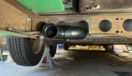
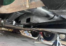
Hmmm....where did we leave off? My waste tanks were cracked and falling apart. This was unknown to me until I bumped the Gray water tank 90° fitting and it fell off in my hands! I ended up getting replacement tanks from Ronco back in April. Went with the same two tank set-up for a Royale, but I missed the fact that the tanks are slightly bigger. So...that meant that the measurements I gave them from the outside edges don't put the slip fittings in the correct spot. That little oversight cost me a BUNCH of redesign and fab time. Specifically, it moved the gray tank more toward the driver side and basically in the path of the black water tank (which is directly under the toilet). After laying on my back for HOURS and cutting out a big section of one cross member for clearance, I'm back on track.

First off, the old tanks were held in with four screws through the plastic flanges. How they hadn't fallen out, I'll never know. I built some supports for the edges of the tanks out of angle iron.

1725135460059.png


1725135482737.png

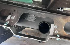
The picture above also shows where Coachman cut the cross-member to adapt to their two tank system vs the factory layout's center outlet.
Here, I've clearanced the cross-member for the jog I had to put in the black water tank outlet to clear my gray water tank.

1725135619599.png

And the plumbing around the Gray tank. I used the skid plate included on my coach to mount my valves. 1725135780533.png

1725135812514.png

Its a bit of a reach under the coach. I'm going to run with it for now and see how it works. If it sucks, I'll change it to a side exit, like it was before.

And Finally, bracing the crossmember to stiffen it back up

1725135950090.png

1725135963030.png

HUGE project that sucked to do, I wasn't expecting to do, but I'm glad I found it while the coach was layed up anyway, vs finding it later.


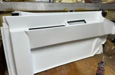
In other news, I'm busy working on plumbing my new LP tanks (Two 20lb tanks in the rear compartment) vs the big ol' 60 Gallon that was right in the middle of my "living room" before. That should be done this weekend (labor day 2024). I'm also working on getting power mirrors installed. I have the wires run to the switches, but need to pull 12v from the fuse box to make them work. I've pulled the cockpit side panels and repaired all the cracks. Then I painted them white to match our lighter, more modern look.


1725136205323.png
 
I have a 78' Royale. Just a suggestion...take a look at this macerator install I did on the 2 tank waste system. Just look at it, maybe it will give you some ideas. I know I got some ideas from your pics about what I should do relative to holding my tanks up. (6 screws with fender washers) Thanks for the pics.

I've been considering a macerator too. Next round of upgrades. I need to get this coach finished! Thanks for the pics.
 
New Propane system is coming along. I have my two 20 lb tanks located in the rear of the coach (where they are on almost every other GMC MH) and my new QD take-off installed to run my BlackStone for outdoor cooking. I have a half inch gas line run to the kitchen in the coach to supply my water heater and Furnace. We eliminated the propane cooktop and oven, and went to an induction cooktop. We won't ever be "baking" in the coach, so the oven is wasted space. Plus we have a convection oven microwave that does a decent job, plus an air fryer/toaster oven combo.

I need to finish up my copper lines to the two appliances in the kitchen, then install Adel Clamps to hold everything in place. At that point, I think EVERYTHING under the coach will be done for this round of modifications.

1728654277636.webp

1728654290929.webp

Some may ask "why?" Well, the propane tank on a Royale 26' is located RIGHT in the middle of the coach and its HUGE (something like 65 lbs capacity). We hardly use propane. So having that much doesn't make sense. It also made it nearly impossible to have a nice lounging area...since the cubby for the tank stuck out in the middle of the floor plan. It was a good place to put a dinette, but that was about it. We want a couch, which meant the tank has to go.

The other consideration is filling that monster tank. Its not easy, and requires the coach be driven somewhere to be filled. These 20 lb tanks have exchanges almost anywhere now. Yes, it is a more expensive way to get propane, but the convenience is worth it to me.

I'm excited to be done under the coach. Next step is getting electrical in...which really shouldn't take me too long, its started. Then spray foam, then plumbing (all being replaced with PEX), then we start the "fun stuff" as my wife puts it.
 
That looks like where the egr valve would be. However, that's likely tapping into the exhaust passage connection that runs through the intake from the cylinder heads. You have to remove the intake to see the ports. That is where the block off plates are installed. One for each cylinder head. Over at the oldsmobile sites they talk about filling the passage in the head with melted aluminum. I'm not there yet but it's something to consider.
 
Late to the party here, but I noticed in your Aug 31/24 posting that you have your waste tanks mounted to the frame. I'm not sure about upfitters but my '77 Palm beach has the black tank mounted to the body. There is some movement between the body and the frame as you drive down the road. I also mounted my macerator to the body so there was no movement between it and the tank.

Just something to think about.
 
  • Like
Reactions: Mike_H
New Propane system is coming along. I have my two 20 lb tanks located in the rear of the coach (where they are on almost every other GMC MH) and my new QD take-off installed to run my BlackStone for outdoor cooking. I have a half inch gas line run to the kitchen in the coach to supply my water heater and Furnace. We eliminated the propane cooktop and oven, and went to an induction cooktop. We won't ever be "baking" in the coach, so the oven is wasted space. Plus we have a convection oven microwave that does a decent job, plus an air fryer/toaster oven combo.

I need to finish up my copper lines to the two appliances in the kitchen, then install Adel Clamps to hold everything in place. At that point, I think EVERYTHING under the coach will be done for this round of modifications.

View attachment 11924

View attachment 11925

Some may ask "why?" Well, the propane tank on a Royale 26' is located RIGHT in the middle of the coach and its HUGE (something like 65 lbs capacity). We hardly use propane. So having that much doesn't make sense. It also made it nearly impossible to have a nice lounging area...since the cubby for the tank stuck out in the middle of the floor plan. It was a good place to put a dinette, but that was about it. We want a couch, which meant the tank has to go.

The other consideration is filling that monster tank. Its not easy, and requires the coach be driven somewhere to be filled. These 20 lb tanks have exchanges almost anywhere now. Yes, it is a more expensive way to get propane, but the convenience is worth it to me.

I'm excited to be done under the coach. Next step is getting electrical in...which really shouldn't take me too long, its started. Then spray foam, then plumbing (all being replaced with PEX), then we start the "fun stuff" as my wife puts it.
A number of folks do what you've pictured regarding the portable BBQ tanks, just be aware that it's not legal in all states.
 
Late to the party here, but I noticed in your Aug 31/24 posting that you have your waste tanks mounted to the frame. I'm not sure about upfitters but my '77 Palm beach has the black tank mounted to the body. There is some movement between the body and the frame as you drive down the road. I also mounted my macerator to the body so there was no movement between it and the tank.

Just something to think about.
That's a good point Bruce and honestly one I hadn't thought about. Based on the amount of clearance there is between the floor of the coach and the connecting pipes, I think it will be OK. I will keep an eye on it though.
 
I like your bracket but it's not going to help much unless you gusset the four corners as shown in red below, or at least the two that are in the same plane as the C channel (front edge). Otherwise that bracket will just open and close like a spring.

View attachment 11926
That's a good idea Todd. Kind of embarrassed I didn't think of it. To be fair, I patterned my bracket off the factory GMC one in the center of the coach, which also doesn't have gussets,
 
  • Like
Reactions: tmsnyder
Some more Updates. Been keeping up on another site...and not here. Shame on me. I'll get this current.

Next project is getting the dash taken care of. I bought some powered remote adjustable mirrors. The old mirrors were manual adjust and they were impossible to reach from inside the motorhome. So, if they were set up for me, and then we changed drivers, it was a giant PITA. The power adjust is a much needed and welcome addition, even with the amount of work installation is. Honestly, without having the rest of the coach pulled apart, I don't know that it would be possible to install them.

First order of business was to run the wires. There are 5 wires per mirror (3 for the motor and 2 for the heater) which have to be routed to the controls. The controls were never intended to be installed in a GMC, so I had to figure that out too. Finally, what I thought would be a minor issue, turned out to be kind of a pain, and that was picking up a non-switched 12V supply. I've had the control wires run for a bit now. That was the easy part.

I also redesigned the Map Pocket inserts in the "door" cards to be a bit more useful. When this was a new vehicle, paper maps were the only type of maps you had, so the pockets they included in the side panels in the cab were pretty useless. Very narrow and very deep. Great to stuff an atlas or Gazetteer in, but not so great for sunglasses or phone. I redesigned them to be a bit shallower, since I am planning on an in-dash GPS, and need more useful storage when were driving. I'll have to get some pictures of those. I 3D printed the new pockets and also included the mounting area for the new Mirror controls.

Last couple days, I've really been focused on getting the mirrors wired up and working. You'd think it would be a piece of cake to grab 12V from somewhere...but there really isn't much of anything that is "live" without the ignition being on, and I decided I wanted the mirrors to be "hot" all the time. Since I was installing a new radio anyway, and radios ALWAYS have a 12V battery feed, I decided to pull that. Well, that was installed in an area that required pulling the whole dash apart...No pictures because, like everything, the dash is broken and falling apart. I do have pics of the damage.

1732512257616.png


Missing piece circled in Yellow
1732512335084.png


That plastic "birdcage" in the lingo of GMC'ers is all ABS plastic, which is 47 years old and very brittle. Its holding all the gages, the radio and heater controls, all the idiot lights, and every other control necessary to interact with the coach while driving.

I did get the radio out, and found the wire I thought I wanted to use. It was only protected with a 10 amp fuse though, and the mirrors need 10 amps, just for themselves. Back to the drawing board. After studying the wire diagrams, I decided to pull my power from the main ignition wire. Its very heavy gage, and protected by a fusible link. I installed a separate 10 amp fuse that I can use specifically for the power mirrors. Felt good to get these things moving.


And as I'm looking at wires...I find a bunch of splices done by previous owners. Most look like this.

1732512847046.png


And they have a single flap of electrical tape wrapped around them. No joke. I've said it before, but I'm still amazed that this coach hasn't burned to the ground yet. Since I keep finding these, I am going through all the wiring in the dash. Found an age related issue in the Speedometer....a couple of the pins that control the lights (not sure which yet) on the PCB have broken off. Not sure how I'm gonna fix that yet

1732512993453.png

1732513002220.png


And I'm cutting all those terrible splices out and replacing them with non-insulated step-down butt splices and some adhesive lined shrink tube. That is about done. I need to hook up one more item and I think that will be complete.

Next step is to rebuild the plastic frame for the dash panel to mount to. I'll get the plastic reassembled, then I think I'm going to get some sheet metal to reinforce it. Maybe a piece of 1/4" plywood, but I think bonding some sheetmetal with Epoxy will fit the dash bezel and pads better. I'll probably replace the speedo with another, used one (will need to look into setting the milage on a mechanical Odometer) and I need to mount the New Single Din, Joying 7" android radio. We'll see how much I get done this week, since I took the week off to work on this project, specifically.
 
Got some more pictures of the dash area, from further away so everyone can see the disaster I'm working on, LOL.

1732558461165.png


1732558478453.png


And, the refurbished door cards...These were just as broken as the dash is now, at one point.

1732558530121.png


The angled hole is where my air suspension controls go, and the long, skinny hole is where my map pockets were. These are the new, 3D printed storage cubbies that I made. The one with the two holes in it will be the driver's side that holds the mirror controls. Need to finish up the "bodywork" on them and get them sprayed white like the rest of the panels.

1732558736256.png


I also found a site that makes reproduction circuit boards for the Speedo and "other" gages (Temp, Fuel, Oil pressure are in a single unit)

https://premiumdashdecals.com/shop/...k-skylark-gs-speedometer-gauge-circuit-board/

https://premiumdashdecals.com/shop/...rally-pack-fuel-oil-temp-gauge-circuit-board/

While not terribly expensive, I eventually want to replace the gages I have with a full complement, including a tach, so I'm going to try my darndest to fix what I have to avoid spending money on something that will not be used in the future. However, Its good to know these exist. I'll monkey with what I have today, and by tonight have a direction.
 
SUCCESS!!! I played around with the gages tonight, and I think I fixed em! I measured the pins that were broken last night, and they were about 0.090" in diameter. All day today, I've been thinking about stuff that was about that size. Went to ace, looking for some 2-56 screws...They had them, but poor selection and they were EXPENSIVE. They only had stainless, and wanted like 0.50 each...which is dumb. Plus, I wasn't sure what kind of clearance I had for screw heads. I scrapped that idea...and then it hit me like a ton of bricks. Why not use some solid strand copper wire? Something like a single line out of a 3 conductor piece of romex. It just so happened that I had a small piece of Romex left over from running power to my pool. It was 8/2, with a 10 ga solid ground conductor. Well, 10 Ga solid wire is about 0.095" Ø. It was perfect. Couple minutes with a file and the wire spinning in my drill and I had the wire sized.

First I had to knock out the old, broken crimp. This is one of the broken terminals.

1732584388671.png


Once the holes were opened up, I fit the new piece of copper. In this picture, I had already soldered one in. That was the test piece, and I was a little sloppy with my solder (as you'll probably see in subsequent pics). Its cleaned up now. Notice the shiny stuff...That is "sticky flux." It helps hold components in place when you're soldering, as well as protecting the joint from oxidizing.

1732584431921.png


Two Pins, Soldered (yeah, the first is a mess)

1732584558117.png


And Finished. All told, I fixed three pins on the speedometer and two more on the other gage (fuel, Temp, Oil press)

1732584626210.png


1732584653741.png


As much testing as I can do out of the coach, It appears these will work just fine now. The real test will be when I go work on it tomorrow and try plugging them in. Will need to see how the fit feels and if the connector fits easily. Trying to keep the pins straight up and down was challenging.
 
Not as much done today. I was busy all day, but kinda spinning my wheels. This morning, I took the gages apart. A friend mentioned that my method would work, but since the board only had copper traces on one side, the pines were only really attached to that trace and the only thing keeping them ON the board was the adhesion of the trace (which is almost nothing), and the friction of the slight press fit between the phenolic and Copper. So, I made some "washers" out of copper, drilled a 3/32 hole in them, and soldered some backers to the pins. That will stop the pins from pulling through if I ever decide to remove the connector harness again. I've made up new curse words reviewing the electrical work done from Previous Owners in this coach, so I wanted to make sure that I am a better steward.

1732673679066.png


After that, I went to the storage location, and tried the gages there. Good news! The connectors plugged in. I'm convinced they will work. Next, I used some ABS pipe cement and started piecing my dash supports back together.
1732673936205.png


The black lines in this picture are glue joints that are already cured and thankfully holding pretty well. The theory behind using ABS cement is that its designed to use solvent to melt the two pieces together. I wanted to rebuild a single piece, and once that is done, I will reinforce the structure with some aluminum or something. Not quite sure yet how I'm doing it. Fiberglass is an option as well. I also used a heat gun to straighten out some of the structure that has warped over time. Heat the plastic until flexible, clamp it to something flat, let it cool. Thermoplastics like ABS will take a "set" in the new arrangement. Not much memory.

The section with Blue tape on it is the missing piece that I re-created. First, I got as much assembled as I could, and took some measurements. I used some clamps and blocks to Hold the gap to the proper amount. Then I used a piece of cardboard to trace the opening left by the missing piece. Overall, It was a piece just under 3" long

1732674174125.png


Then I used the picture above and imported the picture into my modeling program and scaled it to size. I used my spline tool to trace the outline and convert the cardboard picture to a sketch in digital space. Once I had a closed sketch, I made a 3D model.
1732674582661.png


I used that 3d model to create a part file to send to my printer and after a couple hours, I had a new plastic part to pretty closely fit the missing piece in the dash surround. Once the glue is dry, I'll get a picture of the overall fit. It will be easy to see, since its gray, not brown like the surrounding area. Its not perfect, but its pretty good...close enough that I can make up some ABS putty with acetone and plastic to fill the gaps. The one little bit of concern I have is that the ABS filament I have here didn't feed properly in my printer (it was from a Stratasys commercial machine), so I used ASA. They are almost the same material, so I'm thinking the solvent base should work the same, but I'm not 100% sure on that. If it doesn't work, I'll have to order some ABS filament for my printer.

Tomorrow will be mounting the single DIN, 7" Screen Android radio in place of the old Clarion two post model, and hopefully figuring out how to support the plastic surround better. I also have to refinish the front signal buckets, finish the smoothing the new cubbies for the side panels, and shorten, then install the connector bodies on my mirror harnesses.
 
Got a few things done today. Modified the dash for the single din radio. Took a bit of careful trimming and welding, but everything fits well.

IMG_3273.jpeg


The circle to the right of the stereo will get a new USB charger instead of the cigarette lighter the factory installed. @psrivats turned me on to cool gear out of Florida. I got a 75 watt charger from them, and a dual port dash mount.

The dash structure is coming along. Here is the piece i made, glued in. I’ve also slopped some extra material in to fill the gaps. I’ll need to clean it up a bit when it’s all cured.
IMG_3274.jpeg


I spent a fair bit of time today researching and hunting for old parts on EBay. My mirror project required I tap into the from signal /parking lights. The mirrors have side mounted directional in them and the easiest way to get that is to slice into the signal wire up front. The harness runs right by the mirror mount. Anyway, pulling the housings revealed a lot of corrosion…so I was planning on cleaning them up. Just for kicks, I typed the part number into eBay search and for all kinds of NOS assemblies. They were ~200 bucks…so no dice. A couple clicks through the “related listings” though and I found a set for 40 dollars with 32 minutes to go in the auction. I popped a bid in and won them at 40! That saved me a few hours of clean up.

The second eBay find was the mounting panel for my HVAC control. I have a couple broken mounting tabs. Was going to try and use the printer again to make something, but with a little bit more GM cross platform parts shopping, I found a guy selling the exact part I need, which really surprised me, since most people sell the whole HVAC control for about 150-200 dollars. I got this part for 15.

Last bit of figuring I did today was comping up with a replacement for the fiber optic ribbon that illuminates the switch tags in the dash. I’m going to try using some Electroluminescent wire. It’s wire that emits a glow, like neon, but it’s not a” light source “ per se. The kits I found on Amazon use two AA batteries and a transformer to convert the voltage to 90v AC, but very low current. I bought a 5 foot long kit and a 12v Dc to3.1v DC step down transformer, so I don’t need the batteries or switch. I’ll wire the transformer into the headlight circuit so that it comes on with the lights and illuminates the tags. Or, that’s the plan, anyway. First time playing with this technology…so I went cheap. If it works, I’ll develop the thought further and buy higher quality parts.

https://www.amazon.com/dp/B08FB6SMFV?tag=wranglerorg-20
 
Well, the dash supports are coming out. It broke again on me a couple days ago. Kind of a bummer, but its the "right" thing to do. In the meantime, I've been working out the little electrical issues I have and finishing up all my additions. So far as I can tell, I've gotten rid of all the terrible splices. Those have all been replaced with crimp style, uninsulated butt connectors and adhesive lined heatshrink.

My mirror project is 100 percent complete. All wires shortened, connections made, and wires routed and tied down. I tested my new electronic flashers (two, because for some reason, the hazards are on a separate relay from the signals) and those are working. They need to be fully installed though. The power and load leads plug right in, but the electronics need a ground. I'll also need to find a place to mount them.

I need to clean up the signal wires running to the front grill. I have a couple new grommets to install and some loom to protect the new wires. My new signal lights should be here late next week. I do need to clean up / replace the terminals for that circuit. They are pretty green and dirty.

I've also been working on the EL wire project. Here is the old fiber optic braid...this picture shows it MUCH brighter than it really is...3 sec exposure! The bright spots are breaks in the fiber.

1733018036057.png


This is the EL wire I'm replacing it with. Much more consistent light and much brighter (camera had instant exposure).

1733018166782.png


Unfortunately, I screwed something up modifying it to be "dash Lights" and rendered it inoperable. I took the board out and installed a step down transformer, that had a 12V input and a 3.3V output. I also jumped the power switch, so it would automatically turn on when power was applied to the unit. I had it working, but one of my solder joints wasn't good enough. I tried to fix it, and it wouldn't turn on again. I don't know what I did, but I somehow took out the AC transformer (or its just a shit part). So, I ordered another one. I also found a power supply/AC transformer in one this time, so I can just plug the EL wire into power supply that accept 12 volts, and not worry about modifying a circuit board again.

Finally, I've been working on the Dash Face. This is the "wood grained" faceplate that covers all the inner workings of the dash.

Here you can see it in all its 70's fake woodgrain glory

1733018919618.png


There are 4 screws across the top of the faceplate. You remove those and pivot the faceplace down toward the floor, and there are 5 little tabs along the bottom to keep it in place (I bet you all know where this is going). Well, to the surprise of no one, those tabs are broken. Not all of them. Thankfully, one was in good enough shape to model it. I created a new one in my modeling software with a 0.500 x 0.750 baseplate and the hook geometry from the original. Here they are, fresh off my printer (printed from ASA filament).

1733019397660.png


To install them, I used a punch and a matching template that fit on the original hooks.
1733019340756.png


I traced the template with a series of dimples from the punch, so I could sand the chrome without loosing the position of the hooks. You can see a couple dimples here after sanding
1733019506278.png


Finally, a little bit of ABS cement and they are "fixed"

1733019551463.png


And, all 5 of them replaced.

1733019632678.png


I have a screw hole up top that needs repair, and I'm sure you can see the broken plastic circle there on the lower right. I'll fix those up by hand (just some ABS sheet and standard tools) and this guy will be ready to install.

Finally, I need to work on the radio harness. I have the rear camera installed, and the wire run to the front of the coach. Speakers wires are all set (since I'm not doing anything crazy here). The original 8 track, AM/FM mono or optional stereo only used a ignition source 12V supply, since they didn't have an electronic memory to maintain. The Factory radio power circuit only has a 10 amp fuse on it, but they used 14Ga wire(!) so, that will be plenty big enough for me to use for the new radio (200 W). I'll just have to put a 20 Amp fuse in radio slot and change the call-out. The new radio will also need a constant 12V supply. Somewhere along the line, the factory radio was replaced with a Clarion two post. That used a battery supply 12V as well, which was picked up off the Cig Lighter. I'll probably copy that, though that circuit will be running my new USB power supply instead of a cig lighter. I'm searching for the "correct" terminal to use for the old, factory connector. There is an empty slot, and it would be cool to run the Batt (+) through the original connector.
 
Since I have decided to replace the dash supports...I'm fighting hard to not go off the deep end and replace the dash now too...I kinda know what I want to do, based on the old Trans-Am Territory Motorhome that Hagerty did an article on recently.

https://www.hagerty.com/media/autom...ut-a-firebird-on-an-rv-to-mark-its-territory/

In it, they mentioned that the builder installed a trans am gage package. When I saw the pic, I KNEW that was what I wanted to do. It looks period correct, and gives me most of the data that I've been wanting (mostly a tach, but I really want a trans temp gage too.)

TransAm Gauges.png


Obviously, I'm going to deviate a bit, since I'm running in dash nav/back-up camera, but the rest is pretty spot on. I'm not a huge fan of the steering wheel, I like more of the Buick GNX style (I also have a soft spot in my heart for G-bodies). Still three spoke, but no holes. The factory used flat stock, three spoke

1733076165238.png


Some nice Repo/upgrades are out there, like this one. Get the right center cap, and I think this could look pretty good in there.


1733076120114.png


And Trans Am Gage cluster are surpisingly reasonable on Ebay...For example...This one is only 125 bucks. They are all mechanical, so I'm not too worried about getting a "dud."

1733076258349.png


Couple add on's for less than 100

1733076343968.png


And the only additional gage that I would want is trans temp...That would have to tuck in somewhere. Those are the plans anyway. I'm starting by replacing the awful wood with some engine tool vinyl wrap.
1733076638436.png


I think the dash mod is going to have to wait at this point...I can spend a TON of time working on this, while the rest of the moho just sits and wastes away. "Bike Shedding" I think is the term here, LOL. In fact, posting here is probably a form of bike shedding too.

And with that, my 3d Printer just finished, so I guess I better get to getting on.
 
been working on the dash over the last couple weeks, and I'm about ready to start reassembly (after the new year). My beauty panel came out pretty well. Its not perfect (I see the flaws) but it was good practice for the trans am style I'm eventually going for.

1734449770073.png


Also, my identifier project is coming along. The tags printed on my new printer incredibly well. Been tweaking the snap fits and I ordered some ABS filament, since its a bit more flexible than PLA.

1734449731923.png


1734449750577.png


My progress was slowed a bit, since I helped my wife with a furniture refinishing project she took on. I need to get a couple pictures of it. We refinished an old Lane Foot locker cedar chest from the late 60's. Walnut veneer with cedar lining. The bottom was all particle board, so I got some solid walnut and made a new base for the cabinet to sit on. The cabinet also had a small shelf mounted on the lid supports that would lift and remain level when you raised the lid. That piece was VERY rough and smelled of cigarette smoke. We rebuilt that whole thing with walnut and some 1/4" ply.

We delivered it last night...but we're heading to Florida for the holidays, so progress will still be slow for a bit. I'm working on finishing my dash tag retrofit kit (need a couple more parts to lock in the EL wire behind the panel). Then I'll have TWO products to sell to that community. If anyone has a good idea other than Etsy or Ebay to sell things, I'm all ears.
 
Drivers side dash is out for either repair or replacement. I’m heading down the path of repair and reinforce the one I have.
IMG_3555.jpeg


Another update is the my electric-luminescent wire update works very nicely.

Lights off. These are my 3d printed tags that snap in.
IMG_3537.jpeg


And with the EL wire on, behind the tag.
IMG_3536.jpeg


I’m super happy with how they’ve turned out.

More to come as I pick up steam.