1978 Royale Update and Restoration

The first thing I tackled was the rear cap. Its in the worst shape, being that its in two pieces vs what it should only be one!

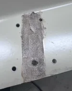
I got my plastic welder and some stainless steel mesh out and got to work. The mesh holds the two pieces of plastic together and reinforces the repair. This the front cap (I don't have pics of the rear), but the process is the same.
1680302026331.webp

This is the front of the repair. With this big of a repair area, I needed to sand the crack back flat due to sagging. I used some polyester body filler (Bondo) to smooth things out.
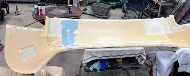
1680302145243.webp

Since I had to sand on the class A surface, I had two choices...Sand the WHOLE THING smooth, which didn't sound like any fun at all, or figure out a way to duplicate the molded texture. I experimented with some Rustoleum bed liner. I've used it on the fender flares and other plastic pieces of my jeep and I had a pretty good suspicion it would work.

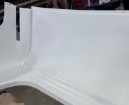
Before painting, I scrubbed it with a burgundy scotch brite pad and some Ajax with bleach. This was to remove any trace of mold release, oil, grease, etc that might be on the surface. After, I wiped it with a microfiber and some rubbing alcohol. Finally, I used some adhesion promoter to prepare the surface for paint. Here is the whole Cap, painted with bedliner.
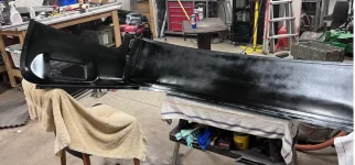
1680302316033.webp

After the bedliner had time to dry, I used some plain, satin white Rustoleum 2x White spray paint. Covered pretty well, and the repaired area is nearly invisible.
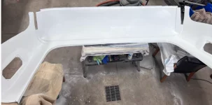
1680302578928.webp

1680302591123.webp

Here is a close up of the textures. This is the original.

1680302621125.webp
And my repair

1680302649451.webp

Overall, I'm VERY happy with how this turned out. The rest of my plastic is in better shape (well, its in one piece at least). I have the front cap nearly ready for paint. All my cracks are repaired aside from two areas that are recessed where the curtain slider extrusion fits. The plastic was stretched a bit too thin in that area when molded. I have some polystyrene sheet on the way to build the area up. I also decided to buy new cockpit trim pieces from Alex Sirum. One of mine is missing and the other is not great.
 
I, too, am very happy with how that turned out. Well done.
I think you'll like those little LED puck lights too. I put some in our house about 5 years ago and we really liked them. We had them in a soffit that connected some cabinets, and had them wired into the under-cabinet 12V LED strips to supplement the dim space between cabinets. The wife highly approved, so what more could a guy want?
 
  • Like
Reactions: Mike_H
This is something I've been working on in my 'free time" off and on. I found old engineering drawings of the coach (from stuff people have scanned and posted) and worked backwards into a CAD model.
1680962662403.png


This is (was) the layout that my GMC had. It's one of three floorplans offered by Jimmy (which was a division of Coachman). The previous owners had modified it a bit already. The two flat planes in the rear are twin size beds. They were fold down couches in the original floor plan. The shorter "table" looking cabinet by the door used to be a full size liquor cabinet (it WAS build in the late 70s!). The upper cabinet had been removed when we got it (the liquor storage). So...the only place for us to sit and relax (like if its raining, or when we visit family and just need to get away) is the dinette. We would put a small TV on the old liquor cabinet...but there was never a good place to store the TV, the dinette, even though it folds into a bed / chaise lounge, isn't very comfortable, and it's just not working for us. Plus, the kitchen cabinet does not use the space it takes up efficiently at all.

My wife and I have has some pretty long discussions and have spent a LOT of time looking at different things people have done with their GMC's We have an idea of what we want now...but before I go crazy building cabinets and removing more stuff, I want to make sure we can make it all fit. The model I built is close...like I won't be able to make prints or anything off it, but it will let me throw some new layouts in and check to see what it will "look" like before I make any sawdust. Its also representative. I don't have all the details in it, more of a sketch than anything else, but its the most efficient way I know of to get my wife (who can't "see" things in her mind like I can) to see it and be able to add her ideas.

Interestingly enough...I can see a pretty nice bumper pull trailer design here too, if a person were to get a couple coaches and cut them up...I have the exterior walls in the model, just have them show as transparent above. Here they are, not transparent. I also don't have the front and rear caps drawn, because those are a low value use of my time (tough to model and won't really help with the overall floorplan design). But two rear endcaps and some framework would make for a VERY nice, 23'ish foot long travel trailer. Might be a bit heavy, but for the cost of a couple parts coaches...and some time....

1680963933109.png
 
  • Like
Reactions: Kendra
Which file format are you using? If you don't mind, I'd like use your CAD model as a starting point for mine. I want to stay close to OEM layout with just a few mods, create accurate drawings to hand to a cabinet maker.

Mine isn't a Coachman but the key is being able to re-use the wall curves from your drawings.
 
Which file format are you using? If you don't mind, I'd like use your CAD model as a starting point for mine. I want to stay close to OEM layout with just a few mods, create accurate drawings to hand to a cabinet maker.

Mine isn't a Coachman but the key is being able to re-use the wall curves from your drawings.
Kenda,
I was able to get a template of the wall curve by using a piece of plywood cut to the height of the door. Then hold the plywood against the side of the door jamb and trace the curve of the wall to the plywood. I then cut the plywood to the curve line for a template.

That's how I made the jig for my curve-hugging window valences.

 
  • Like
Reactions: Kendra
Bruce that's a great idea. I remember reading your window valence process but didn't think of applying that to accurately curve the cabinets.

I might end up using a cabinet maker with modern CNC-based cutting equipment, but a template opens up the potential to work with smaller shops. Both methods can use a template to build replacements before the originals are removed.
 
Bruce that's a great idea. I remember reading your window valence process but didn't think of applying that to accurately curve the cabinets.

I might end up using a cabinet maker with modern CNC-based cutting equipment, but a template opens up the potential to work with smaller shops. Both methods can use a template to build replacements before the originals are removed.
Don't forget about the "middle-age bulge". So your wall curve may not be the same as the next coach's.
There is a grid showing the wall curve with the CAD drawings on Billy's site.
 
  • Like
Reactions: billvv
Which file format are you using? If you don't mind, I'd like use your CAD model as a starting point for mine. I want to stay close to OEM layout with just a few mods, create accurate drawings to hand to a cabinet maker.

Mine isn't a Coachman but the key is being able to re-use the wall curves from your drawings.
It’s drawn in Inventor. Until I prove this model though, I’d rather not share it. I’d hate for you to trust it, then have someone cut something and it be incorrect. I drafted it from the drawings on Billy’s site. I don’t have the link to the actual drawings, but I can share the files with you. Send me a pm if you’d like them.
 
  • Like
Reactions: Kendra
Been looking at power systems the last couple days, reading LOTS of information on LiFePO batteries, Inverter/Chargers, and BMS. I don't really have a good house bank right now. Coach came with 1 group 24 battery that worked and one group 31 battery that was garbage for my house.

Since I need to buy batteries anyway, I'm going to pony up for Lithium. However...there is a pretty steep learning curve and a WHOLE lot of information out there...and no way to know what is good or not. I posted this, but it hasn't gotten a lot of traction.


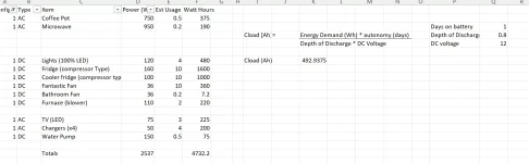
I worked up a bit of an energy budget tonight and it seems a bit excessive. I don't know if I'm over estimating my power requirements, time, or just using too much juice. Right now, I'd need about 500 Ah's to last 1 day on battery. Based on ~$600 for 100 Ah of Lithium...well, my batteries would be my single biggest purchase I've made on the ol girl yet! That's just batteries too, I still need my Inverter/Charger, some sort of monitor for the system and a DC-DC charger to help charge while I'm running the main engine. It is also undetermined if I will need to replace the Delco Alternator with one of those fancy Balmers with an external regulator. Read a bit about load dumps and how the LiFePO BMS will basically cook every alternator plugged into them. The DC-DC charger buffers some of that, but it also means slower charging. Oh, and don't forget the wiring...there is a whole bunch of copper that needs to be purchased to wire all this stuff up. Those battery lugs ain't cheap either!

If anyone has any feedback, I'm all ears.

Thanks

1681871067452.webp
 
  • Like
Reactions: ScottC
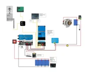
Been working on the power system design and have started to order "stuff." This is a (very small) representation of what I'm planning on. This layout gives me shore power and Generator (through an auto transfer switch) to feed the Victron Multiplus 2 3000VA 120v Inverter/Charger. I've included a 30 amp DC-DC charger to run off the starter battery and charge my lithium pack when the motive engine is running. I will be replacing the old "squareD" residential style breaker box with one from progressive dynamics that is set up to have two feeds. The Inverter/charger I picked has two AC outputs. One is pass through only, and will only power items on that branch when plugged into shore power (like the AC units). The other branch will supply inverted AC from the batteries. Speaking of Batteries, I decided on 400 AmpHours (4x 100 amp hours) from Epoch. They have gotten VERY good reviews everywhere I've looked and they are relatively inexpensive for a heated LiFePO battery (about $500 each). They have their own BMS. This system also gives me room to add solar in the future. Based on my energy budget (updated since the last one I've posted), the set-up should give me just over a Day of runtime (350 amp hours with a 20% overage calculated in) if we are pretty wasteful with our energy consumption.

1683252574758.png
I'm very happy with how this has worked out. I'm over budget about 10%, but it will be a VERY nice system when complete. I could certainly do it less expensively, but I'm doing this for the long game. I'm cribbing a lot of the techniques and materials from the Marine world as I believe the marine and RV spaces share a lot of the same challenges but risk of failure is higher for marine.

I will be placing the orders for my Victron stuff soon. Once I have it all in my hands, I'll work on the layout and order my battery cable and terminals. Something else not shown, and kind of the budget buster, is the Cerbo GX monitor system I will include. The Cerbo will replace the OE control panel in the coach. It will display all the battery information, control my inverter, display up to 4 tank levels (with a couple add ons), it can send an auto start signal to the genset, if I so desire, etc. Very neat and it displays all the information on a 5 or 7 inch screen (like a small tablet).

Now that I have this stuff figured out, I will get back to work on cleaning the rest of the interior, running my circuits, etc.
 
Last edited:
  • Like
Reactions: ScottC
New stuff is starting to roll in. Got my new AC distribution box, my DC-DC isolated charger, and my monitor and screen. Saturday, we went to an airstream dealership for "inspiration." They also have a very well stocked parts department. I'm thinking at this point, were going to do horizontal curtains for our windows vs the tried and true day/night shades. The horizonal sliding curtains on the airstreams was very nice and my wife and I both liked it. Plus, as I have two VERY wild animals that stay with me (or dogs with separation anxiety). I think the curtains will be much more durable. Looking at the extrusion airstream uses for those curtains, I believe it will be a very nice set-up when finished.

Speaking of set-up, I think we've decided on our floorplan...but its still digital, so who knows. I've designed 4 or 5 different lounge areas so far and like this one the best.

1683551566798.webp

1683551575251.webp

It allows for a nice area to watch TV if the weather is crummy, I should be able to make the table fit into the center section and have a spot for extra people to sleep, and it make use of some pretty wasted space currently (where the blender and a couple drawers are in the rear lounge Royale floorplan).

I will also design the lounge to be more useful for storage. Stuff like a jack, tools and spare parts can go under the cushions. I'm really trying to get to a point where the rooftop carrier can come off...but until I have all the new storage in, I don't want to pull it yet.

Yesterday, I worked on cleaning up all the mess of wires and poorly maintained electrical in the back of the coach. Got all of that stripped out and back to the circuits. Everything is labeled and ready to got back when the inverter and batteries show up. Based on some of the stuff I found, my wife and I decided that the bath module and kitchen cabs are coming out as well.

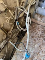
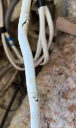
This is the latest in a series of terrible things I've found regarding the wiring in my coach

1683552040056.webp

1683552054537.webp

It was covered with black tape, so someone knew they did it, but didn't fix it properly. I also found melted and broken connectors on the air pump. That connection basically fell apart in my hand when I removed the tape holding it together. I NEED to get into the rest of the coach and make sure I don't have any other fire hazards. That pump connection probably explains why it takes so long for my bags to fill also...I'm sure the pump was only getting a percentage of the voltage it requires...and generating a TON of heat in the process.

The joys of a 45 year old rig....
 
  • Like
Reactions: pvfjr
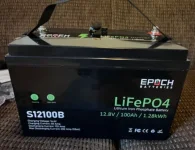
Batteries showed up yesterday.

1683761372224.webp

This is a heated battery, with its own BMS, for 500 bucks. Pretty inexpensive and based on the information at Marine How-To its a damn good battery too.

For reference, a Victron of comparable capacity is over 1000 dollars and you still need to buy the BMS. These Epoch's do NOT have bluetooth accessibility (they make a version that does, however, for an additional $100 to the purchase price) but since I plan on using a shunt and the Cerbo GX, I'll be able to monitor them through the Victron App. Each battery also came with its own remote "fuel gage" that I'll incorporate into my mounting system so I can make sure that one battery isn't providing all the juice or something.

Its getting exciting around here!
 
  • Like
Reactions: pvfjr and Popofsix
Got the battery try built over the last few weeks (June is ALWAYS such a busy time for us). The drawer turned out really well, and I plan on using some 1" wide Polypropylene straps, Footman's Loops, and cam buckles to secure the batteries to the tray.

Here is a Mockup
1687143179505.webp

The drawer slide is good for 300 lbs, but the batteries are about 35 each, so I'm well under the limit there. It slides in and out nicely and came with a built in lock

1687143281813.webp

I figured sewing those straps up would be a piece of cake...Boy was I wrong. My mother is a bit of a sewing machine collector / amatuer seamstress and over the years, I've picked up some things and done some projects here and there. I borrowed her oldest Pfaff machine (probably 45+ years old, at this point). It has plenty of punching power (so I wasn't struggling to get through the double layer of strap) but the straps formed such a stiff piece of material, the lock stitches were not working properly. The feed dogs would push the material up, loop the bobbin thread and make a HUGE mess. I tried everything she had, up to and including the newest, latest and greatest Pfaff computerized home sewing machine they make. Even maxing out the presser foot pressure, I got the same result. I was convinced I was going to have to find someone to help me on this project...but then I started thinking.


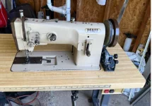
I'm going to have a LOT of sewing to do in the future. I'll either need to pay someone to make cushions for me...which I've done before and it isn't cheap. Or...I can try to find something that I can use to do my own cushions. After a couple days of research and looking at marketplace and craigslist, I found a really nice industrial walking foot machine for sale locally. It was a bit more money than I wanted to spend...but its a REALLY nice machine. Heavy duty, made by Pfaff (one of the best sewing machine companies out there...Singer, Pfaff, and Juki). Its a triple feed, walking foot mechanism, which means the machine always has pressure on the material and the needle is buried when the material is advanced. Its been sitting for 12 years and the guy I bought it from just had it tuned up. Apparently, it was his Dad's and they are getting ready to move his mom into a home. Gotta clean the stuff out of the house. So, its the proverbial "little old lady" car, Very little use, very good shape.

Here it is. Pfaff 1245 industrial

1687144079915.webp

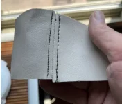
And, some of the stiches it will do. I've done this stuff with a domestic machine and it nothing but frustrating. I whipped these out in about 5 minutes. This french seam was done in very heavyweight vinyl.

1687144139370.webp

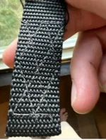
And, the whole reason that the search for a sewing machine started...A practice piece of webbing. This picture shows the backside, which is what I've been struggling with.

1687144221374.webp

I'll get my straps done in the next couple days and get the batteries installed. Then it's on to buying battery cable and lugs and routing all my new circuits I plan to install.
 
Been working on and off on the old girl, trying to avoid the awful heat and humidity we've been having for the last few weeks. But...enough excuses. I tried and tried to get the batteries to fit into the space to the right of the Generator, and make them accessible. Unfortunately, by the time the drawer I built fit the space (and dodged all the screw heads and brackets that also live there) the tray was too narrow and I was worried about shorting the battery posts. I even counter sunk the heads on some of the protruding bolts. I just wasn't comfortable with it, once I got it to "fit".

SO, back to the drawing board...

1689249741086.webp

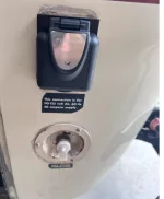
I will arrange them sorta like this, but 90 degrees to their current position (like two rows of two) and build a nightstand of sorts to house all the power equipment. My incoming power conditioning (surge protector/phase and voltage monitor) and automatic transfer switch will mount to the backside of the Gen Housing (inside) and I replaced my shore power cord with a shore power outlet.

1689250223927.webp

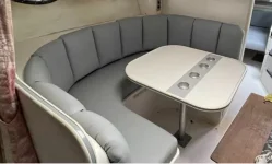
I also found a boat while browsing marketplace one night that had a dining set-up similar to what I'll end up building. I think it will work out. I'll obviously adjust my size to fit the space, and I'll figure out some access to the corners for storage.

1689250324826.webp

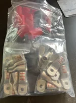
All in all, I'm feeling pretty confident at this point with the direction of this build. Confident enough that I finally bought copper to connect all my batteries and the rest of the DC power side. Copper is SO expensive...if it wasn't a felony, I think I would start melting pennies, as I believe they are worth more buy weight in copper than their actual monetary value! 10' each of red and black 2/0 wire was 9 bucks a foot, and then you need the battery lugs...those buggers are about 3.50 each, and you need a bunch. This will get the batteries connected to each other, the inverter, and through the main disconnect and fuses. 1689250571113.webp


I still need about 25' of 6 gage to connect my DC to DC charger that will live in the engine compartment and replace the old isolator. I will lose functionality of the battery switch this way (LiFePo4 batteries shouldn't be used as starting batteries), but I am going to set up to have two engine batteries, so that shouldn't be an issue. I will also have a separate generator battery and it also has a regulator / rectifier on it (I replaced that when I rebuilt the engine and I checked the stator for open circuits and shorts), so I should be able to bootstrap myself up should I find all the batteries dead.
 
  • Like
Reactions: bdub
May I suggest you install your DC-DC charger close to your LiFePO4 (LFP) batteries. Unless your DC-DC charger has remote battery voltage sensing, you want it as close to the LFP batteries as possible to reduce to the voltage drop between them to a minimum, On the input side of the DC-DC charger, it will compensate for the voltage presented to if after any voltage loss.
Your DC-DC charger will also appreciate being installed inside protected from the elements.
 
May I suggest you install your DC-DC charger close to your LiFePO4 (LFP) batteries. Unless your DC-DC charger has remote battery voltage sensing, you want it as close to the LFP batteries as possible to reduce to the voltage drop between them to a minimum, On the input side of the DC-DC charger, it will compensate for the voltage presented to if after any voltage loss.
Your DC-DC charger will also appreciate being installed inside protected from the elements.
I’ll take that into consideration. I’ve heard (but not confirmed) that the Charger will make up for the voltage drop, ( I guess that’s what you mean by voltage sensing?). It’s a Victron Orion 12-12, 30 amp. I need to confirm that, because to get to a 3% voltage drop situation over that kind of distance, I need 2 ga wire, which is crazy.
 
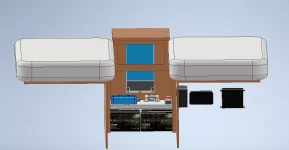
Here's how we're looking so far. I'll do a short drawer up top, and a false front cab door from the floor to the drawer. The PO had a shoddy hinged door and every time I needed to get in there, I fought that stupid thing. It was ALWAYS in the way....there is only 27 inches between the bed frames, and I'm not a small guy (6'2" and about 220 lbs). So, being able to remove the door face entirely will be nice. I'll use some rare earth magnets to hold it on. I will probably make the upper section removable too, just in case I need to pull the inverter out the top or I want to look down on my connections that are positioned on the level above the batteries.

1689353293021.png


The table top will include a couple cell phone charging ports and a place to plug in reading lamps. Having the drawer there will be good too, so we can store our nighttime "stuff" like bite splints, ear plugs, and the other stuff you need when both parties in a couple snore, and you need to choose between drowning out the noise, or smothering them with a pillow, LOL.
 
Been a busy summer, but I'm back at it and making some good, tangible progress. Something to remember tackling a project like this is that every idea you have won't work out as you intended and you sit and think, sometimes for a LONG time without making much physical progress.

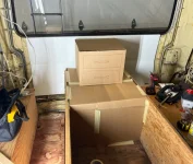
I first made up a cardboard mock-up for my wife's approval. She doesn't "see" things like I do, so a couple extra minutes doing this prevents a LOT of second guessing later on.

1696364845756.webp

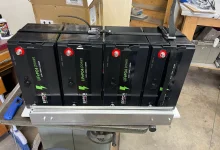
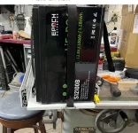
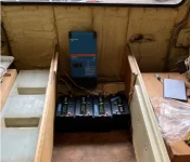
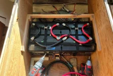
Then I got down to business. Have the batteries mounted here. I have polypro webbing running both front to back and side to side. I also have my batteries wired up in parallel and they will feed the "protection and distribution" section from the inner set of terminals. I also have a frame built to support the next layer. That layer will be hinged to open up and provide access to the batteries.

1696364917084.webp

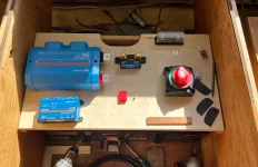
Protection and distribution. I had to order a couple new terminals that have a 90° bend in them to help with wire routing (2/0 gage copper has a pretty large bend radius). The wires will come up thru the elliptical opening and the positive goes to the big fuse holder, then the switch, and on to the lynx distributor. The negative will go to the shunt, then to the Distributor. After the distributor, the wires get smaller and more manageable...But I will have the DC-DC charger, the Inverter/Charger, and my DC power Fuse block for the house system attached to the lynx, with one open slot for my yet to be purchased solar controller.

1696365040744.webp

I feel good about this set-up now, so progress should be happening more quickly again. This was a big brain tax...Had to learn a WHOLE bunch and the planning/integration step was tough to get right, given the small footprint we have to work with.
 
Mike,
I'm envious of your battery system. I have two 100 Ahr LiFePO4 batteries in parallel and they have been great.
If I was doing four batteries, I would have looked into wiring them in series for 48 volts. That reduces the current to 1/4 so that smaller wiring can be used. But the chargers and inverters are typically more expensive because of lower production.
 
  • Like
Reactions: Mike_H