I'm hoping to make it to the Fall Convention.What an eloquent solution. I'd been keen to see the end results when all done.
Sailor Man's Coach: Then & Now
- Thread starter sailor man
- Start date
You are using an out of date browser. It may not display this or other websites correctly.
You should upgrade or use an alternative browser.
You should upgrade or use an alternative browser.

Perhaps...if you can make the fall GMCMI convention...you would condsider doing a tech session outlining the rebuilding of your coach? We'd love to see it.I'm hoping to make it to the Fall Convention.
Initially, ethanol fuel will pass through one of these filters with before and after shut off valves. If that filter becomes fouled, it does not need to be immediately replaced. Just shut off the valves inline line before and aft of the fouled filter.
Open up the valves in front and aft of the 2nd pristine filter and I am back in business.
Can you share with us the make/model of your fuel filters?
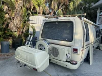
One point, your fuel pumps and fuel filter arrangement are very exposed to damage from road trash thrown up by the front tires and serious damage in an accident. Are you planning on providing some kind of protection for them?
My Birchaven came with an externally mounted fuel pump and filter and had a kludge cover that kept some of the sand and gravel from bombarding it, took 3 different tools to undo the cover.One point, your fuel pumps and fuel filter arrangement are very exposed to damage from road trash thrown up by the front tires and serious damage in an accident. Are you planning on providing some kind of protection for them?
I made a cover-mount from 2 pieces of large leg aluminum angle, one attached to the frame with cradles to hold the pump and filter, and the other angle was hinged at the bottom so it could swing up and cover the side.
The fronts of both angles were cut and bent so they sloped up towards the front leaving a small opening for the fuel line, and the hinged cover was held in place with springs inside aluminum gutter spike ferrules which acted as standoffs. The end of a paper clip was bent to form a hook which catches the spring to unhook it from the cover - semi-tool free, and is stored on the exposed underside of the hose clamp that holds the pump.
The arrangement keeps most of the debris away from the pump and filter - still surprises me how much gets thrown up in there.
Larry:Perhaps...if you can make the fall GMCMI convention...you would condsider doing a tech session outlining the rebuilding of your coach? We'd love to see it.
I would love to do that. My largest concern would be if I could fit everything in a single session.
Perhaps I would try to do an overview and then do additional sessions that specialize on particular sectors.
As an architect, I had to do many public presentations. It's been more than 20 years since i have done that, so I am a bit nervous thinking about it.
Where and when will the fall GMCMI Convention take place?
I hope that it is not to far away from Florida.
I am currently in the design and installation phase. I am afraid that with all of these modifications, the learning curve will be arduous and long. I hope that I will not have to drive the coach a long distance to get to the convention.
Last edited:
Can you share with us the make/model of your fuel filters?
One point, your fuel pumps and fuel filter arrangement are very exposed to damage from road trash thrown up by the front tires and serious damage in an accident. Are you planning on providing some kind of protection for them?

This filter is marine grade, so it is much more robust than the normal automobile filters.
I actually have been thinking about some kind of debris protection. I think that the the filter is the most vulnerable component.
All of the hoses are high pressure fuel lines, so they are much more robust than the normal low pressure ones.
All of the fasteners, hose clamps, valves, and plumbing fittings are stainless steel. They are quite strong and corrosion resistant..
The black plastic mounting plate is Starboard and nothing sticks to it. It is also waterproof and uv resistant.
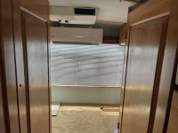
AS I keep think about hoot make the kitchen area the most useful, I have come up with the latest version.
View attachment 18077
This version is using a very large Dupont Corian Farmers Sink in Cameo White fused in with the Corian countertop.
In order to maximize the counter surface, I plan to sever the bottom of the caress seat back next to the sink so It can swing up and extend the countertop surface, even reaching the surface of the dining table.
View attachment 18078
If I can make this all work, the kitchen area will be much larger during food preparation and cooking times.
The hugh farmer sink will have a matching cameo white cover that is hinged in the middle to allow sink access while also expanded the counter top surface.
Maybe Claude & I could cook together to prepare a feast to be served in the coach or outside.

This is the latest version of the kitchen area. The photo illustrates how the counter extension should work.
The counter extension does not quite reach the table, so there is no instruction. I just need to make certain that it clears the cypress seat back as it swings up.
I am using a smaller sink as well.
In order to deal with the garbage and recycling, I plan to use the empty storage space under the dining table bench for a slide out Rev-a shelf (2) 35 qt garbage/recycling cans with lids.


It is a perfect location to the right of the sink.
I am going to have to shorten the garbage can to fit into the space.
It is a perfect location to the right of the sink.
I am going to have to shorten the garbage can to fit into the space.
I made a cover-mount from 2 pieces of large leg aluminum angle, one attached to the frame with cradles to hold the pump and filter, and the other angle was hinged at the bottom so it could swing up and cover the side.
The fronts of both angles were cut and bent so they sloped up towards the front leaving a small opening for the fuel line, and the hinged cover was held in place with springs inside aluminum gutter spike ferrules which acted as standoffs. The end of a paper clip was bent to form a hook which catches the spring to unhook it from the cover - semi-tool free, and is stored on the exposed underside of the hose clamp that holds the pump.
The arrangement keeps most of the debris away from the pump and filter - still surprises me how much gets thrown up in there.


Finally, for the very first time we were able to activate the new Lithionics 51.2vdc 300AH system.
It has taken us 3 years to make this happen!
Inovation is sometimes so daunting.
I have not seen it myself but Jacob texted me about it. I generally start working sometime between 2:00 & 5:00am to prepare Jacob for the days work ahead. By 4:00 in the afternoon I am generally toast and am in bed. Whatever Jacob completes after that, I will see the next morning.
The (2) mini splits are working. We have gotten E6 & E7 error codes, so we probably need refrigerant gas. Next for the servicing.
We have not yet turned on the 455 to test the Balmar 48 volt, 60 amps alternator, but there is so much excitement! Things are coming together and the equinox is not far off. The sun is getting stronger in Florida and we soon will have to start hiding from it.
Getting all the coach's new direct current air conditioning systems functioning will be a blessing.
Until the mini-splits are gassed up and fully functioning I will not be able to determine how well the design is.
Attachments
Here are the specification for the 2 YMGI Mini-Split Systems.View attachment 18237View attachment 18239View attachment 18240
Finally, for the very first time we were able to activate the new Lithionics 51.2vdc 300AH system.
It has taken us 3 years to make this happen!
Inovation is sometimes so daunting.
I have not seen it myself but Jacob texted me about it. I generally start working sometime between 2:00 & 5:00am to prepare Jacob for the days work ahead. By 4:00 in the afternoon I am generally toast and am in bed. Whatever Jacob completes after that, I will see the next morning.
The (2) mini splits are working. We have gotten E6 & E7 error codes, so we probably need refrigerant gas. Next for the servicing.
We have not yet turned on the 455 to test the Balmar 48 volt, 60 amps alternator, but there is so much excitement! Things are coming together and the equinox is not far off. The sun is getting stronger in Florida and we soon will have to start hiding from it.
Getting all the coach's new direct current air conditioning systems functioning will be a blessing.
Until the mini-splits are gassed up and fully functioning I will not be able to determine how well the design is.

The indoor sound level is rated at 42 or below dB(A). That is very quiet!
What is the sound level in your coach? My Apple watch can tell you what it is.

Dam Quiet.

Can you imagine having this type of environmental control in your coach?
Pretty Nifty but it took more than 3 years to make it happen.
It has been so very difficult to keep this under my hat for all these years.

As bought but the small folding table on the sofa was between the driver and passenger seat.

And recently


The kitchen is starting to come together.
I may need another knife holder.
Too many knives!
Sammie, our Portuguese Water Dog is inspecting her sometimes home on wheels.
I have been trying to work my way through the wiring in the coach and then implementing my new electrical design.
I downloaded the original GMC Electrical Plans and then decided to print it out. It took about 9 separate pdf's to print out (9) 8 1/2"x11" sheets to bind them all together, end to end. I had the total print out, black and white, which is now rolled up around an old cardboard roll from a paper towel. At lest I can roll out the entire drawing to see what is what.
However, I am still pulling out old unused wire to get rid of the rat's nest of ancient wire.
The new electrical system bears little resemblance to the original wiring. I decided to start from scratch to put together a plan that will allow anyone to track down things in the new arrangement. Instead of using a black and white drawing with electrical symbols for components, I decided to try to use photos of the components connected with colored lines of various thickness to make it easier to find myself around the diagram. I think it will help the people I may hire to work on the couch for me or future owners.
The diagram is a work in progress and it will take some time before it is finished but I think that you might like to see where I am at now.
It is being easier to to work through the system to determine if the design will work. There are components using one or more of these types of communication to work together and all require programing to function as I am intending. It will be great if there are not too many bugs and clashes. I hope that nothing burns out.
(5) Programble Automatic Transfer Switches for either alternating Current or direct current or both.
(2) Sterling Battery to Battery Chargers
(2) Victron MultiPlus II inverter/chargers
(2) Victron SOC (State of Charge Controllers
Multiple Fuses and Fuse Blocks
Multiple Circuit Breakers and Breaker Panels
(2) Alternators with dedicated Smart Remote Regulators
(2) 48vdc Mini-split Heat Pumps
(2) Lithionics 51.2vdc LiFePO4 Batteries with provision for a third battery
(1) Litionics Remote BMS system using dedicated IonBus can bus comunications
New Custom Electric Power Center
Etc., Etc, Etc.........
There are bluetooth, wifi and internet communications
Not all of the components are on the diagram yet, but here it is.....
View attachment 17202
Can you follow it?
Do you have any suggestions on a way to make it more clear?
I intend to expand the set by providing blow ups of the components the various detailed wiring to see all of the connections. This diagram is primarily concerned with batteries, changing systems, conversion between alternating current and direct current and various voltages.
I am going to add the current protections for the fuses and breakers. You are looking at ac and dc wiring.
AC: 120v but portions can use 120/240v
DC: 12 v
48v
51.2v
In actual use, the voltages vary considerably.

In order to actually find out what the original factory wiring was like, I printed out the original wiring diagram on (6) 8.5"x11" sheets and pasted them together.
Sorry about the semi circular smudges!
This is the base line and this layout doest no include some of the factory options.
At least it is a start.
I started to color the wires so that I could understand it better, but I just got too tired to finish it.
In order to get my final diagram, I I need to ring out all of the wires now in the coach.
They include the original wiring, wiring by previous owners, wiring done by Cliff and of course by by Jacob and me.
I hope that this image will help you.
It may be the first time you have seen this all in one piece. This is 11" wide & 51" long.
Attachments
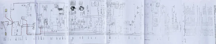
Certainly easier on the eyes!View attachment 18267
In order to actually find out what the original factory wiring was like, I printed out the original wiring diagram on (6) 8.5"x11" sheets and pasted them together.
Sorry about the semi circular smudges!
This is the base line and this layout doest no include some of the factory options.
At least it is a start.
I started to color the wires so that I could understand it better, but I just got too tired to finish it.
In order to get my final diagram, I I need to ring out all of the wires now in the coach.
They include the original wiring, wiring by previous owners, wiring done by Cliff and of course by by Jacob and me.
I hope that this image will help you.
It may be the first time you have seen this all in one piece. This is 11" wide & 51" long.
Alan Henderson, Ken's son that now runs their electric wiper business, sells very large format (2'x10' and even larger) electrical diagrams for most GMCs including those by upfitters.
Really a great bargain and huge timesaver.
View attachment 18267
In order to actually find out what the original factory wiring was like, I printed out the original wiring diagram on (6) 8.5"x11" sheets and pasted them together.
Sorry about the semi circular smudges!
This is the base line and this layout doest no include some of the factory options.
At least it is a start.
I started to color the wires so that I could understand it better, but I just got too tired to finish it.
In order to get my final diagram, I I need to ring out all of the wires now in the coach.
They include the original wiring, wiring by previous owners, wiring done by Cliff and of course by by Jacob and me.
I hope that this image will help you.
It may be the first time you have seen this all in one piece. This is 11" wide & 51" long.

This is the condition of the fuses in the glove compartment as I found them. There are (3) additional circuits piggy backed on other the original fuses. In addition, there are (4) glass fuse blocks with fuses and an additional black box with more wires. The only one that I am certain of the the red piggy backed wire on the left which seems to power the previous owner's electrical fuel pump.


I decided to replace all of the glove box fuses with circuit breakers. Here I am checking out if I can get 24 breakers in.

It does not fit like this.

But if I trimmed the circuit block ends a bit, I could get (2) 12 circuit blocks in.
Since we do not use paper maps any more with GPS, the glove compartment is way over sized.
 Rather than stuff (4) of these to get (48) 12vdc breakers, I decided to add (2) 6 breaker panels for a total of 36 breakers.
Here I am using various angled connectors so I can put together compact color coded harnesses to the breaker block.
 Notice the trimmed ends.
This was the original 12vdc loads for the fuses in the Electrical Power Center Copayment. With no Furnace, recirculating toilet or 12v range hood in the coach, very little dc power fuses were being used.

With all of the new equipment now using 12vdc, I hope that 45 breakers will be enough. There were only 17 fused when new.
Last edited:
HVAC guy came yesterday and verified that there is refrigerant in the system. However, the system did not start up. We are getting Code 6 & 7 errors which seem the be related to communication issues not power. Working on it.. Me HVAC said that it should start up if we get the communications right.View attachment 18237View attachment 18239View attachment 18240
Finally, for the very first time we were able to activate the new Lithionics 51.2vdc 300AH system.
It has taken us 3 years to make this happen!
Inovation is sometimes so daunting.
I have not seen it myself but Jacob texted me about it. I generally start working sometime between 2:00 & 5:00am to prepare Jacob for the days work ahead. By 4:00 in the afternoon I am generally toast and am in bed. Whatever Jacob completes after that, I will see the next morning.
The (2) mini splits are working. We have gotten E6 & E7 error codes, so we probably need refrigerant gas. Next for the servicing.
We have not yet turned on the 455 to test the Balmar 48 volt, 60 amps alternator, but there is so much excitement! Things are coming together and the equinox is not far off. The sun is getting stronger in Florida and we soon will have to start hiding from it.
Getting all the coach's new direct current air conditioning systems functioning will be a blessing.
HVAC guy came yesterday
Until the mini-splits are gassed up and fully functioning I will not be able to determine how well the design is.
Sailor Man, It is so good to see someone who really cooks in their GMC. We have big, fancy meals and savor every bite. Maybe we just like to nest, but a full kitchen, with salad spinner, garlic press, good knives and all the rest means that even with limited counter space, a fancy meal is a treat for us both. Really happy to see someone else with the cooking gene. Well done!View attachment 18265
The kitchen is starting to come together.
I may need another knife holder.
Too many knives!
Sammie, our Portuguese Water Dog is inspecting her sometimes home on wheels.
View attachment 18320
This is the condition of the fuses in the glove compartment as I found them. There are (3) additional circuits piggy backed on other the original fuses. In addition, there are (4) glass fuse blocks with fuses and an additional black box with more wires. The only one that I am certain of the the red piggy backed wire on the left which seems to power the previous owner's electrical fuel pump.
View attachment 18321View attachment 18322
I decided to replace all of the glove box fuses with circuit breakers. Here I am checking out if I can get 24 breakers in.
View attachment 18323
It does not fit like this.
View attachment 18324
But if I trimmed the circuit block ends a bit, I could get (2) 12 circuit blocks in.
Since we do not use paper maps any more with GPS, the glove compartment is way over sized.
View attachment 18325Rather than stuff (4) of these to get (48) 12vdc breakers, I decided to add (2) 6 breaker panels for a total of 36 breakers.
View attachment 18326
Here I am using various angled connectors so I can put together compact color coded harnesses to the breaker block.View attachment 18327Notice the trimmed ends.
View attachment 18329
This was the original 12vdc loads for the fuses in the Electrical Power Center Copayment. With no Furnace, recirculating toilet or 12v range hood in the coach, very little dc power fuses were being used.
View attachment 18328
With all of the new equipment now using 12vdc, I hope that 45 breakers will be enough. There were only 17 fused when new.

I am color coding each breaker and will be using harness with Anderson connectors. Each breaker capacity is identified. These are not switches. If a breaker overloads and breaks the circuit, just push down on the white dot and the breaker will reset.