Well there's a good example of Timken not getting it right! Good reference @Richard RV . I'd only seen this with SKF and National, so that's good to know Timken isn't perfect either. My suppliers have never had those available anyway, so I was hopeful when he said he'd sourced Timken seals.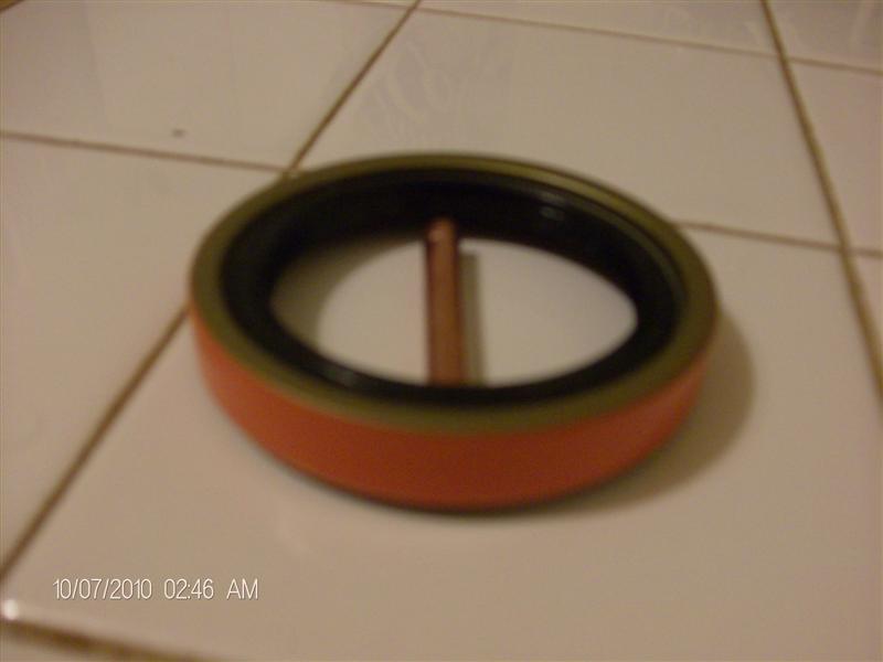
New Bad Timken Rear Wheel Bearing Seal
With the 1/4 inch od tube rolled under the rubber it kicks the seal up off the table. I just purchased this seal at Autozone yesterday. It will be going back tomorrow. If you have an old seal, take it with you when you buy a new one and show them how the 1/4 in. od tube should roll under it. It...www.gmcmhphotos.com
Greasing rear wheels
- Thread starter nighthawking
- Start date
You are using an out of date browser. It may not display this or other websites correctly.
You should upgrade or use an alternative browser.
You should upgrade or use an alternative browser.
Jim K new rear spindles for $750
Dave Lenzi was very through when he addressed this issue of the seals. He tried several brand seals and didn't find one that worked.
I made up an adapter plate to keep the rear seal .030" proud


Dave Lenzi was very through when he addressed this issue of the seals. He tried several brand seals and didn't find one that worked.
I made up an adapter plate to keep the rear seal .030" proud
Last edited:

Dave Lenzi sells (or was selling) an aluminum disk with a machined recess to properly install the rear seals.Dave Lenzi was very through when he addressed this issue of the seals. He tried several brand seals and didn't find one that worked.
I made up an adapter plate to keep the rear seal .030" proud
Question: to verify satisfactory performance, will an IR heat gun show elevated temperatures if there is a problem? If so, at 5 miles of use from install, 100 miles?
If one has done this work with the bearings, does 100 miles with no issues after service indicate a satisfactory install? 1000 miles?
Trying to weigh warnings and not have to nanny this idea while giving it significance.
If one has done this work with the bearings, does 100 miles with no issues after service indicate a satisfactory install? 1000 miles?
Trying to weigh warnings and not have to nanny this idea while giving it significance.
Yours is a lot nicer than my shade tree method, Bruce. I drove the seal in most of the way, then used a flat washer of the correct thickness as a spacer held against a wood block, and tapped the wood with a mallet as I moved it around the hub until the seal was evenly seated.Jim K new rear spindles for $750
Dave Lenzi was very through when he addressed this issue of the seals. He tried several brand seals and didn't find one that worked.
I made up an adapter plate to keep the rear seal .030" proud
View attachment 17950
View attachment 17951

It's always a good idea to check hub temperatures often. An IR gun gives the most precise temperature readings, but you can also just touch the wheel - rears should be roughly similar temperatures and the fronts should be roughly similar temperatures. If there's a discrepancy break out the IR gun and start monitoring more frequently.Question: to verify satisfactory performance, will an IR heat gun show elevated temperatures if there is a problem? If so, at 5 miles of use from install, 100 miles?
If one has done this work with the bearings, does 100 miles with no issues after service indicate a satisfactory install? 1000 miles?
Trying to weigh warnings and not have to nanny this idea while giving it significance.
This is not just for verifying post-installation, it's also for heading off a wallet-biopsy. It can't hurt you to do it and most certainly can if you don't.
That's a tough call. The lips on the seal have very little thermal mass. As they get ground down, the energy required to destroy them is minimal, and the heat generated would just sink into the hub assembly without being noticed. Now there's finely ground steel impregnated in the grease. It's going to start doing its thing to the bearings, but it's probably pretty finely ground, so I don't know how quickly the bearings would start failing and start heating up. As Richard said, at this point it might just fall under "it's always a good idea" to monitor temps to predict any imminent failure.Question: to verify satisfactory performance, will an IR heat gun show elevated temperatures if there is a problem? If so, at 5 miles of use from install, 100 miles?
If one has done this work with the bearings, does 100 miles with no issues after service indicate a satisfactory install? 1000 miles?
Trying to weigh warnings and not have to nanny this idea while giving it significance.
When I bought my wrecked Palm Beach I had it towed to my friend's tow yard, then replaced the destroyed steering box and drove it home 10 more miles. We did a wheel-lift tow, figuring everything was fine in the back, as this was a running/driving/camping coach at the time of the accident (presumably). We didn't hear anything during the tow, but I could hear this bearing from the driver's seat during that 10 mile drive home! To think the PO was happily traveling around like that...
I guess good hearing is a blessing. Without it, you'd better have an IR gun handy.

Yours is a lot nicer than my shade tree method, Bruce. I drove the seal in most of the way, then used a flat washer of the correct thickness as a spacer held against a wood block, and tapped the wood with a mallet as I moved it around the hub until the seal was evenly seated.
View attachment 17953
This is the way to go.
I'm not going to carry a special tool around for this seal considering the limited onboard storage.
I cleaned and greased the rear bearings on the Kingsley. Either the threads on two of the nuts or spindle shafts were damaged as I was not able to hand tighten, so I torqued and backed off and used the deep socket in hand to snug down on nut. I didn't think it was over tightened. Test run of 30 miles and after parking motorhome on driveway I noticed that the front right intermediate wheel was tilted in at the top. When I removed the wheel, I found that in just thirty miles the outer bearing disintegrated and the inner race welded to the spindle. Called Sirum and they shipped me a good used spindle with a new nut.Question: to verify satisfactory performance, will an IR heat gun show elevated temperatures if there is a problem? If so, at 5 miles of use from install, 100 miles?
If one has done this work with the bearings, does 100 miles with no issues after service indicate a satisfactory install? 1000 miles?
Trying to weigh warnings and not have to nanny this idea while giving it significance.


I cleaned and greased the rear bearings on the Kingsley. Either the threads on two of the nuts or spindle shafts were damaged as I was not able to hand tighten, so I torqued and backed off and used the deep socket in hand to snug down on nut. I didn't think it was over tightened. Test run of 30 miles and after parking motorhome on driveway I noticed that the front right intermediate wheel was tilted in at the top. When I removed the wheel, I found that in just thirty miles the outer bearing disintegrated and the inner race welded to the spindle. Called Sirum and they shipped me a good used spindle with a new nut.
That's unfortunate, it sounds like you installed it too tight b/c of the buggered threads. With a buggered up thread you won't be able to feel that zero lash point with your fingers. My favorite miniature file set includes a barrette file which is triangular and perfect for cleaning up buggered threads. That plus new nut and you should be able to get the spindle fixed so the bearing can be properly installed.
In case someone that's new to dealing with bearings wants to learn to do this, the overall procedure in a nutshell is to get the bearing installed just barely loose.
Here's how I do it at least, same as on a trailer axle, or front wheel on a rwd truck or car, or tractor front axle, ... etc anything that's just a simple spindle and pair of bearings.
The method puts everything tight together but not so tight to damage the bearing. Less than 'snug' with your wrench, like maybe 1 ft-lb. This pushes the grease out of the way and gets all the metal bearing parts 'tight' together. Then back off the nut, careful not to move the hub, and immediately finger tighten until you find the zero lash point, then back off to the next available notch in the castle nut and insert the cotter key.
I have this bearing packer, it works well especially when I place it in my hydraulic press to force out the old grease and flush through the new grease. Takes hardly any effort at all and you get to watch it happen:
Todd, the maintenance manual has a very different procedure, so I'm not quite sure what you meant.In case someone that's new to dealing with bearings wants to learn to do this, the overall procedure in a nutshell is to get the bearing installed just barely loose.
Here's how I do it at least, same as on a trailer axle, or front wheel on a rwd truck or car, or tractor front axle, ... etc anything that's just a simple spindle and pair of bearings.
The method puts everything tight together but not so tight to damage the bearing. Less than 'snug' with your wrench, like maybe 1 ft-lb. This pushes the grease out of the way and gets all the metal bearing parts 'tight' together. Then back off the nut, careful not to move the hub, and immediately finger tighten until you find the zero lash point, then back off to the next available notch in the castle nut and insert the cotter key.
1) Torque nut to 25-30 ft-lbs while turning the wheel at least 3 revolutions.
2) Back off nut and re-tighten finger tight.
3) Insert cotter pin into 1 of the 2 available spindle through-holes, and if neither allows the cotter pin to be inserted back off (only!) the castle nut to the first available hole.
Todd, the maintenance manual has a very different procedure, so I'm not quite sure what you meant.
1) Torque nut to 25-30 ft-lbs while turning the wheel at least 3 revolutions.
2) Back off nut and re-tighten finger tight.
3) Insert cotter pin into 1 of the 2 available spindle through-holes, and if neither allows the cotter pin to be inserted back off (only!) the castle nut to the first available hole.
Yes that's the same except are you sure the torque is 30 ft-lb? That seems excessive.
Even if the cotter key fits in after step 2 and you don' t need to back off the nut to the next available spot that means there's space for the pin to go in and the nut can turn outward opening the lash required.
I found this in the 1976 maintenance manual page 4-28:
11 . Referring to Figure 18, install brake drums and hubs on spindle. Tighten castilated nut (figure17) to 25-30 ft . lbs., back nut off one half turn and then finger tighten until cotter pin can be installed.
No mention of rotating the wheel while the bearings are tightened at 25-30 ft-lb
The part that's most important is that the bearing is not installed 'tight', with zero lash. It's installed just slightly 'loose'
Last edited:
I posted earlier in this thread the photo site diagram showing the seal sitting proud, it also has the rear hub torque procedure.Yes that's the same except are you sure the torque is 30 ft-lb? That seems excessive.
Even if the cotter key fits in after step 2 and you don' t need to back off the nut to the next available spot that means there's space for the pin to go in and the nut can turn outward opening the lash required. The bearing will be 'not tight', which is the critical point.

I posted earlier in this thread the photo site diagram showing the seal sitting proud, it also has the rear hub torque procedure.
View attachment 17968
Source?
The 0.001" - 0.005" end play is the looseness needed to make the bearing live a long life. Must not be 0.000" (tight). That's the important part but I'm sure no one actually breaks out the dial indicator and mag base to measure this lol.
The source is the maintenance manual and those wild and crazy GMC engineers! The procedure is in the manuals, and also all over both old and new forums - a couple such:Source?
The 0.001" - 0.005" end play is the looseness needed to make the bearing live a long life. Must not be 0.000" (tight). That's the important part but I'm sure no one actually breaks out the dial indicator and mag base to measure this lol.
https://www.gmcmotorhome.org/threads/rear-bogie-spindle-nut.73899/post-473721
https://www.gmcmotorhome.org/thread...ck-rear-wheel-bearing-73-26.68354/post-428771
And this one in that same thread from my favorite pedantic mechanic quoting the manual:
https://www.gmcmotorhome.org/thread...ck-rear-wheel-bearing-73-26.68354/post-428776
I'm actually surprised (and thankful!) that torquing to 1 ft-lb hasn't caused you grief, Todd.

The initial 30 ft/lb torque is to ensure the bearings, seals, etc are fully seated.
I've done more rear bearings than I count and my procedure has always been to apply some torque (I always do it by hand - maybe 5 ft/lbs?) to the final bearing install. In my (vague) way back memory, I recall a rolling torque measurement and it being different for new bearings vs regreased. I can't imagine leaving any cone bearing even a little loose.
I've done more rear bearings than I count and my procedure has always been to apply some torque (I always do it by hand - maybe 5 ft/lbs?) to the final bearing install. In my (vague) way back memory, I recall a rolling torque measurement and it being different for new bearings vs regreased. I can't imagine leaving any cone bearing even a little loose.
The source is the maintenance manual and those wild and crazy GMC engineers! The procedure is in the manuals, and also all over both old and new forums - a couple such:
https://www.gmcmotorhome.org/threads/rear-bogie-spindle-nut.73899/post-473721
https://www.gmcmotorhome.org/thread...ck-rear-wheel-bearing-73-26.68354/post-428771
And this one in that same thread from my favorite pedantic mechanic quoting the manual:
https://www.gmcmotorhome.org/thread...ck-rear-wheel-bearing-73-26.68354/post-428776
I'm actually surprised (and thankful!) that torquing to 1 ft-lb hasn't caused you grief, Todd. View attachment 17969
Because 0.000" = 0.000" ;Tight is tight. Once the steel surfaces are touching there's no reason to put more force on it. So I don't and would never put that much on it.
And the end result is exactly the same.
I asked for the source bc there's no rotating the wheel mentioned in the 1976 maintenance manual that I posted. But the one you posted says to back off nut 1/2 turn _while rotating_ and that would cause the bearing to open up and ruin the procedure. The way it reads to me, the wheel should be rotated at each step in that procedure. If someone does it that way, it won't be correctly done. And no one is going to break out the dial indicator to measure the 0.001-0.005. So I was just curious where it came from. I imagine anyone working on these at the time didn't even read the method bc its literally something people do as a child wrenching on their bikes getting the front wheel bearing set up properly. Its a similar setup. But today, it's less likely that someone would have experience with this, it's more likely they would have bolted on a replaceable unit bearing.
Rotating the wheel while applying the specified torque setting is GMC's standardized method to insure that everything is in full contact. The backing off and finger tightening is there to provide the correct clearance. The method is not wrong and it's not complicated. As always, your coach, your call.Because 0.000" = 0.000" ;Tight is tight. Once the steel surfaces are touching there's no reason to put more force on it. So I don't and would never put that much on it.
And the end result is exactly the same.
I asked for the source bc there's no rotating the wheel mentioned in the 1976 maintenance manual that I posted. But the one you posted says to back off nut 1/2 turn _while rotating_ and that would cause the bearing to open up and ruin the procedure. The way it reads to me, the wheel should be rotated at each step in that procedure. If someone does it that way, it won't be correctly done. And no one is going to break out the dial indicator to measure the 0.001-0.005. So I was just curious where it came from. I imagine anyone working on these at the time didn't even read the method bc its literally something people do as a child wrenching on their bikes getting the front wheel bearing set up properly. Its a similar setup. But today, it's less likely that someone would have experience with this, it's more likely they would have bolted on a replaceable unit bearing.
That first forum link does have incorrect information. After loosening the nut the wheel is NOT to be moved and the nut is tightened by hand and the cotter pin installed.
The GMC manuals do have some variances between the different editions, vehicle weights being one of them. Those don't really affect the operation or longevity of a coach, but the wheel bearing procedure certainly does.
Good catch, Todd. Thanks.

Rotating the wheel while applying the specified torque setting is GMC's standardized method to insure that everything is in full contact. The backing off and finger tightening is there to provide the correct clearance. The method is not wrong and it's not complicated. As always, your coach, your call.
That first forum link does have incorrect information. After loosening the nut the wheel is NOT to be moved and the nut is tightened by hand and the cotter pin installed.
The GMC manuals do have some variances between the different editions, vehicle weights being one of them. Those don't really affect the operation or longevity of a coach, but the wheel bearing procedure certainly does.
Good catch, Todd. Thanks.
Since we're beating a dead horse....
I looked up the method that Dexter Axle has posted (b/c they are a similar setup) and they are a good quality company that's been making axles for a long time. Note that their instructions use 50ftlb! (I'm really going to have to up my torque game from now on
") ) , the hub is rotated only while torquing to 50ftlb (note the scientific torque spec ' full hand force' LOL, it's backed off and then hand snugged, then BACKED OFF again to the first spot available and specifically installed so the nut is loose and only retained by the pin. IE the whole thing goes together _loose_.
) , the hub is rotated only while torquing to 50ftlb (note the scientific torque spec ' full hand force' LOL, it's backed off and then hand snugged, then BACKED OFF again to the first spot available and specifically installed so the nut is loose and only retained by the pin. IE the whole thing goes together _loose_. https://www.dextergroup.com/user_area/content_media/raw/LDServiceOnline.pdf on page 56
Bearing Adjustment and Hub Replacement
If the hub has been removed or bearing adjustment is required, the following adjustment procedure must be followed.
For standard grease or oil axles using cotter pin:
1. After placing the hub, bearings, washers, and spindle nut back on the axle spindle in reverse order as detailed in the previous section on hub removal, rotate the hub assembly slowly while tightening the spindle nut to approximately 50 ft-lb (12" wrench or pliers with full hand force)
2. Then loosen the spindle nut to remove the torque. Do not rotate the hub.
3. Finger tighten the spindle nut until just snug.
4. Back the spindle nut out slightly until the first castellation lines up with the cotter key hole and insert the cotter pin.
5. Bend over the cotter pin legs to secure the nut.
6. Nut should be free to move with only restraint being the cotter pin.
Seems like a good topic for a seminar at a GMCMI rally based on our spirited discussion
Beating a dead horse... Well, yeah, it's called tenderizing!Since we're beating a dead horse....
I looked up the method that Dexter Axle has posted (b/c they are a similar setup) and they are a good quality company that's been making axles for a long time. Note that their instructions use 50ftlb! (I'm really going to have to up my torque game from now on
https://www.dextergroup.com/user_area/content_media/raw/LDServiceOnline.pdf on page 56
Bearing Adjustment and Hub Replacement
If the hub has been removed or bearing adjustment is required, the following adjustment procedure must be followed.
For standard grease or oil axles using cotter pin:
1. After placing the hub, bearings, washers, and spindle nut back on the axle spindle in reverse order as detailed in the previous section on hub removal, rotate the hub assembly slowly while tightening the spindle nut to approximately 50 ft-lb (12" wrench or pliers with full hand force)
2. Then loosen the spindle nut to remove the torque. Do not rotate the hub.
3. Finger tighten the spindle nut until just snug.
4. Back the spindle nut out slightly until the first castellation lines up with the cotter key hole and insert the cotter pin.
5. Bend over the cotter pin legs to secure the nut.
6. Nut should be free to move with only restraint being the cotter pin.
Seems like a good topic for a seminar at a GMCMI rally based on our spirited discussion

If we hadn't been flogging the pony you wouldn't have caught the error in that graphic and in that earlier forum post that erroneously instructed to rotate the wheel while hand tightening the nut. So kudos for that, Todd!
I'd probably seen that graphic posted ten or twenty times and, sad to say, never read it closely. I know what the manual says and the first lines of the graphic's written instructions were right, so I just skipped the rest I guess.
You also wouldn't have gone down the rabbit hole to find Dexter Axle's instructions if we weren't having this give and take, yes? Totally a win-win. That's why we have these discussions.
Now I want to address your poor choices in oil and tires...