Looking for help and support with EBL Flash system

wait what?
Does this apply to the Tach signal from an HEI distributor?
I'm pretty sure I just ran it directly to the ECM
I should have prefaced this by saying I started with a Howell system. Howell's wiring harness had a small interface board that buffered the 12V pulses from the TACH connection on the HEI coil down to 5 volt (TTL compatible) pulses. This is the same board that some on GMCNet incorrectly said it was was to "fool" the 7747 into thinking it was connected to a knock sensor.

The EBL board MAY have included a buffer that allowed direct connection to the 12V tach pulses.
 
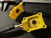
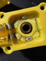
Well I am happy to report that after replacing the reed switch in the speed sensor and wiring it in, it works.

I set the VSS filter to around 60% and played with the VSS PPM setting until I got it almost perfectly matched with the speedo at 50 MPH. it starts out high with being about 5mph over at 15-20mph but evens out at around 50.

It's not yet calibrated with the wheel size, but those will change in the future when we are able to find some factory steel 15" rims for the truck.

Now I need to get me a RPM meter to check weather the EBL or the tach is correct, they are about 300-400RPM off from each other and gets worse the higher the rpm gets. I can rev the engine where the tach is up to 3000 and the WUD will show up to 4000+ RPM. at idle the tach sits around 600 and WUD shows 750-800. to my ears the idle seems a little low so I am leaning more toward the tach being correct.

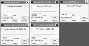
I believe I saw a setting in tunerpro for adjusting the RPM other than the "number of cylinders" setting. there are three RPM settings that I can't find any documentation on as well. Not quite sure where to set the engine idle speed or how the RPM filter works.

1773110595375.webp
 
The IAC Idle Speed scalar sets the idle speed at start and until the when the ECM goes into closed loop (WUD reports when closed loop is active). Once CL is reached, the other settings tell CL what the set point should be and CL uses the VE table to calculate the injector pulse width. If the IAC has to open or close fully it can no longer control RPM; at that point you have do the IAC/throttle plate setup procedure.
 
  • Like
Reactions: dbrannon79
Tonight I verified the RPM between the WUD and what was showing on the factory tach. I had an old tach in my parts bin, temporarily wired it in at the battery and poking a wire in at the distributor. fired the engine up and that tach is matching what the EBL is showing.

I need to see if the factory tach is adjustable on this old 68 C10. I think I saw an adjustment screw on the back of it, but I will have to pull the cluster out again and see. we must have been running 3500 RPM doing 70 on the freeway on the last trip! last thing I want is to red line this engine and think I still have a little more it can go, especially since my will be driving it (his truck). I want to get everything functioning properly for him.
 
Yesterday while I was working on calibrating the speed on the EBL I noticed that the knock counts were climbing up like crazy on the WUD. up in the 3000+ count range. strangely I could not hear anything unusual from the engine while holding the RPM steady at around 1500-2000 (according to the dash tach) no rattles from the body or the exhaust though the knock counts were steadily climbing.

Just how sensitive are these knock sensors? and should I be worried about that? I have tried light taps on the block near the sensor with the engine off and the WUD did not pick up anything then, but I was just using the head of my screw driver, not a heavy object.

If the knock sensor is bad or failing, which one should I get? is there a specific one I need to replace it with? I don't know what the part number is for the one installed, but just in case it's not the right one or is a cheap Chinese knock-off I would like to get the right one, have the part number information. that and the O2 sensor as well. If my son ever needs to replace parts it would be awesome to put that info in the glove box as well as crating a list to put on the USB drive I am putting together for him on the tune for this truck.
 
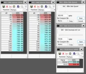
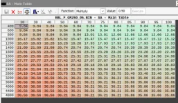
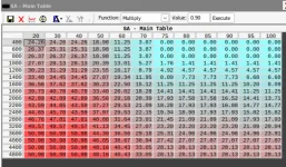
I need some help! I have what might be a dumb question here. I have been studying the SA main table and comparing it to the table set by the PO along with tables from other base files in the EBL software. it occurred to me that I might have been looking at the tables backwards as to how it's displayed.

question I have is... which end of the table is WOT and which is "idle state" I just want to make sure I am looking at it correctly.

Here is two screenshots, first one is the current table I am using, the second one is the table that was setup by the PO when we got the truck. keep in mind that I moved the distributor from 16deg to 8deg along with changing the SA Initial from 0.00 to 8.09. at idle I am seeing in WUD the map sensor reading around 40kpa

I have been assuming the map reading correlated to this table but I might be mistaken. looking at other sources online this table reads "Absolute Kpa" rather than "Vacuum Kpa" to RPM. if that is true, then I am looking at these tables backwards!

1773197265357.webp

1773197281575.webp
 
100 Kpa is approximately standard atmosphere pressure at sea level. So Wide Open Throttle (WOT) is about 100Kpa and idle is about 20-30Kpa.

At least that is what I understood, but I could be all wrong!
 
  • Like
Reactions: dbrannon79
So in theory, full load WOT on the table would be 4800 RPM at 100Kpa (bottom right on the table). the colors tunerpro puts on there are misleading in my head. I see the higher the number the more "red" it gets but that's not WOT area. those areas in the bright red would only seen on deceleration while in gear (manual trans) where the drive train pushes the engine. This is my understanding, hoping its right LOL
 
Last edited:
On the SA Initial and me moving the distributor. Taking the base timing from 16 to 8 degrees, I basically mechanically took out 8 degrees of timing. Then changing the SA initial from 0.00 to 8.09, I put that 8 degrees of timing "electronically" back in through the EBL. doing this, I allowed the engine to crank and start at 8 degrees instead of the 16, then the EBL took over and added 8 degrees not taking into account the SA idle setting.

The SA idle state set at 20 degrees overrides the table while in idle mode.

Am I understanding that part correctly? Just making sure I am wrapping my brain around this right before I even try messing with the timing tables again dealing with the knock counts.
 
Sort of, except as I understand it, 'idle mode' reports throttle position but Closed Loop is what switches the ECM from startup timing to table timing. I've read that this can be a couple of minutes for a non-heated O2 sensor to very quickly for a heated one. You can watch the ClsdLp light on the WUD to see when that happens. You also might get some answers by downloading scsv datalogs using the WUD and looking at them on a spreadsheet. You can use WinLog-EBL to draw graphs from datalogs.

I have been unable to find a location and type of knock sensor that reports something other than no knocks or thousands all the time on my 455, which does not have OEM knock control. If you have a knock sensor and ESC that is OEM for that engine you have a fighting chance.
 
  • Like
Reactions: dbrannon79
Sort of, except as I understand it, 'idle mode' reports throttle position but Closed Loop is what switches the ECM from startup timing to table timing. I've read that this can be a couple of minutes for a non-heated O2 sensor to very quickly for a heated one. You can watch the ClsdLp light on the WUD to see when that happens. You also might get some answers by downloading scsv datalogs using the WUD and looking at them on a spreadsheet. You can use WinLog-EBL to draw graphs from datalogs.

I have been unable to find a location and type of knock sensor that reports something other than no knocks or thousands all the time on my 455, which does not have OEM knock control. If you have a knock sensor and ESC that is OEM for that engine you have a fighting chance.
Closed loop (CL) is the mode where the engine uses the feedback from the oxygen sensor to adjust the air fuel ratio (AFR). The engine can exit CL mode and use other tables and parameters to set the AFR such as in Lean Cruise mode.

The engine starts up with the initial timing setting. When the engine exceeds 400 RPM, the ignition module switches from internal timing signal to the timing signal from the ECM. This is the point the ECM uses either fixed idle spark advance or spark table SA, depending on the BIN setting for idle SA timing.

Other parameters affect the SA, such as Lean Cruise mode.

Or so the story goes...
 
Last edited:
Just how sensitive are these knock sensors? and should I be worried about that? I have tried light taps on the block near the sensor with the engine off and the WUD did not pick up anything then, but I was just using the head of my screw driver, not a heavy object.

If the knock sensor is bad or failing, which one should I get? is there a specific one I need to replace it with? I don't know what the part number is for the one installed, but just in case it's not the right one or is a cheap Chinese knock-off I would like to get the right one, have the part number information. that and the O2 sensor as well. If my son ever needs to replace parts it would be awesome to put that info in the glove box as well as crating a list to put on the USB drive I am putting together for him on the tune for this truck.
The knock sensor module is basically an audio filter "tuned" to the sound of knocks for your engine. From my reading in the past, the knock sound is dependent mostly on cylinder diameter. Here is a guy that makes knock modules. The cylinder diameter of the engine is the only parameter he needs.

The sensor itself is really just a piezo "microphone". I'm not sure to what degree it is "tuned" to the engine.

 
I realized I goofed in post 70 where I said bottom left and meant bottom right of the table. I edited it and corrected it to my other left LOL

I did read about the issues with matching EST modules and knock sensors with the engines they were meant for. since this engine is an old 250, none of it is factory. these engines never came with fuel injection. all were carbureted. I did (the other day) experiment with it wondering if I simply disconnect the knock sensor if it would trigger an error code or just run normally without it. no error code came up and seemed to run without showing any knock counts. I supposed if I can't get the knock counts to calm down I can always leave it disconnected. I just need to make sure the timing is within a range that no damage would occur over time.
 
The knock sensor module is basically an audio filter "tuned" to the sound of knocks for your engine. From my reading in the past, the knock sound is dependent mostly on cylinder diameter. Here is a guy that makes knock modules. The cylinder diameter of the engine is the only parameter he needs.

The sensor itself is really just a piezo "microphone". I'm not sure to what degree it is "tuned" to the engine.

This is very interesting. Could be the answer to all the information I read about others having "false" knocks with mismatched setups or like this truck which never had fuel injection. I will have to look into this. Thank you!
 
The knock sensor module is basically an audio filter "tuned" to the sound of knocks for your engine. From my reading in the past, the knock sound is dependent mostly on cylinder diameter. Here is a guy that makes knock modules. The cylinder diameter of the engine is the only parameter he needs.

The sensor itself is really just a piezo "microphone". I'm not sure to what degree it is "tuned" to the engine.


I've been looking for an ESC ! Bruce is this what you use?
 
  • Like
Reactions: dbrannon79
I managed to find a module that matched the 455 when I did ESC about 15 years ago. I don't recall the part number. a search of the GMCNet archive might bring it up. I'm not at home so I can't look it up for you... sorry.
Where/how did you mount your knock detector? Mine is in the water jacket bung low on the Driver's side.
 
  • Like
Reactions: dbrannon79
Where/how did you mount your knock detector? Mine is in the water jacket bung low on the Driver's side.
My knock sensor is in the water jacket bung on the passenger side, about mid point just above the oil pan. I had to tweak the oil cooler lines bracket to get some clearance.

My knock module is on the engine side of the top passenger side stair riser. Sorry I can't post a photo, coach is 4,500Kms from me at the moment.
 
Last edited:
  • Like
Reactions: dbrannon79