I've made some decent progress as far as weeknights go. I've confirmed that the rear bumper isn't in the way when removing exhaust, but my Glenbrook sure is!

After backing it up a ways, the whole thing came out. I sprayed a little silicone lube on the rubber donuts, and they didn't fight me too much. I didn't even bother to unbolt the brackets or anything. Man is that thing long.

One thing I did fight was an exhaust clamp I hadn't noticed. It was tucked into that rear triangle between the crossmember and the angled gusset/crossmember thing. I yanked on that and spun it this way and that to no avail, and for longer than I'd care to admit (you know, so I wouldn't have to crawl under there again).

With the exhaust out, you can see how all the crossmember holes line up below the bumper and just barely inside the bottom lip of the frame rail as it turns upwards.

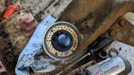
With the exhaust out of the way, it is MUCH easier to access the bogie bracket's bolts.

Double success!

I'll do a mild amount of cleanup, then start stripping down the donor bogies and install them, hopefully this weekend.
After backing it up a ways, the whole thing came out. I sprayed a little silicone lube on the rubber donuts, and they didn't fight me too much. I didn't even bother to unbolt the brackets or anything. Man is that thing long.
One thing I did fight was an exhaust clamp I hadn't noticed. It was tucked into that rear triangle between the crossmember and the angled gusset/crossmember thing. I yanked on that and spun it this way and that to no avail, and for longer than I'd care to admit (you know, so I wouldn't have to crawl under there again).
With the exhaust out, you can see how all the crossmember holes line up below the bumper and just barely inside the bottom lip of the frame rail as it turns upwards.
With the exhaust out of the way, it is MUCH easier to access the bogie bracket's bolts.
Double success!
I'll do a mild amount of cleanup, then start stripping down the donor bogies and install them, hopefully this weekend.
Last edited: