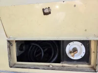
900w on the roof sounds lovely. I’m trying to sort mine out right now and can only figure 650w using 50w flexible panels. What’s your setup look like?Tested my 15K BTU roof-top heat-pump using a 4KW inverter and 280Ah (3584Wh) battery. It starts and runs! In "Turbo" mode (fan and compressor both at "high") I should get around 3.5 hours running non-stop. Hopefully, the compressor will cycle and I will also use a lower setting to increase my duration.
The inverter was drawing a little over 950W from the battery in Turbo (around 260W at lower settings and only 65W with just the fan). With 900W of solar on the roof, at the hottest part of the day most of the power requirements can be met from the panels; increasing the time the system can run. Plus, I will have a second battery on Monday, doubling everything.
I will completely test the system in the real world the weekend of the 11th.
So what did you do to your GMC today?
- Thread starter RvRev2
- Start date
You are using an out of date browser. It may not display this or other websites correctly.
You should upgrade or use an alternative browser.
You should upgrade or use an alternative browser.
the page from my build thread900w on the roof sounds lovely. I’m trying to sort mine out right now and can only figure 650w using 50w flexible panels. What’s your setup look like?
Thank you for sharing.
Over the weekend I ordered a Renogy 3000w inverter w/ auto transfer switch, 4 100w flexible solar panels, 2 additional 100ah Renogy Li batteries from a guy on FB, and a Pioneer 13.5k AC/Heatpump.
I’m planning on splitting my 50a service, running AC, outlets and fridge on the battery powered side. If I need water heater or microwave, I’ll need to be plugged in or running the ONAN.
If anyone is interested in solar panels, Renogy has the black models on clearance at 90/pc

Last edited:
We are installing a new FiTech fuel injection system along with the new 70 gal aluminum tank with new filters and a pair of electrical fuel pumps.
View attachment 15601
This is what the new Jim Bound's COOP 455 looked like with the old carb, distributer and spiderweb electrical wiringView attachment 15602.So far, the new FiTech is in place and the old wiring has been simplified and organized.
We have to fabricate a new throttle bracket (in the foreground) to make the FiTach throttle work in place of the carb.
View attachment 15603
Replacement Throttle Plate.
View attachment 15776
We have blocked off the old port for the old mechanical fuel pump in order to install a pair of FTach electrical fuel fuel pumps along side of each other. They will be wired so that only one of them can work at a time and in the event of a pump failure, the back up pump can be energized by throwing a single switch.
Redundancy.
Although the electrical power from the pump comes from the FiTech control system, these pumps draw 10 to 15 amps @ 12vdc by themselves. This is much more than the original gas pumps used.
According to FiTech, The FiTach unit draws 10-15 amps, the pump, 10-15 amps and the fan 30-40 amps. This is a maximum current draws of 70amps @ 12vdc. Can your alternator handle that along with the other 12vdc needs on your coach?
I have upgraded my alternator to a Balmar 160 amp, 12vdc alternator (red One) controlled by a very sophisticated WakeSpeed remote regulator that is programed to charge a battery bank of (10) BattleBorn 12v 100ah battereis (1,000ah).
I suspect that a lot of fuel injection failure or under performance issues are coming from a limited availab=ility of clean 12vdc current, especially when another device needed 12vdc power starts up. That might cause intermittent problems with the fuel injection system.
The separate DieHard Gold starting battery is charged by a Sterling 12v t battery to 12v battery charger. The DieHard provides 800 CCA to start the engine without drawing current from the FiTech.

Putting in the new 70 gal aluminum gasoline tank.
View attachment IMG_2140.mov
It was a very difficult job. Most of the connections for fittings on this tank are 1/2" not the 3/8" that I expected. There are two places to connect the vent are on top of the tank which make us have to leave some space above the tank. There are now about (14) 3/8" holding the tank in place.
Most coaches come with the exhales pipes running to the rear of the coach, but in my coach, a previous owner diverted the exhaust pipes to come out in front of the door. The tank is offset to the passenger side to allow for the passage of of the exhaust pipes.


This is the plumbing almost ready to be installed between the new FiTech fuel injection system and the the 70 gal aluminum tank. These panels will be fastened to the outside face of the steel chassis to provide easy access if the fuel pumps or filters need to worked on if the filter fouls or the fuel pump fails.
There are (2) high pressure electric FiTech fuel pumps plumbed in parallel. All of the fittings are stainless steel with ethanol capable high pressure hose. Between the (2) pumps and the engine side are stainless steel back flow preventers to protect the pump that is not working. At the dashboard is an electric switch with 3 positions.
Up Pump #1 On With amber led pilot light
Center Both Pumps off Anti theft device
Down Pump #2 On With red led pilot light
Both pumps cannot not be function at the same time.
In case of a fuel pump failure or under performance, throw the switch to activate the second pump.
There is a pair of filters plumbed in parallel. The pale yellow filters placed st the ends will replace the plumbed bright yellow filters. The new filters are Racor 025-RAC-02 filters with a 10 micron and 25 gal per hour rating. There are shut off valve on each side of the filter so that an auxiliary fish filter can be used by flipping the 4 valves. Then, after completing the trip, a spare filter can replace the old fouled filter. At least I will not be stopped on the side of the road by a fouled filter.
I will only be using pure gasoline with no ethanol.
I finally got around to repairing my gas strut support job on my generator door. While I had the bar stock for that repair, I also used some of that bar stock to manufacture a prop for my power cord/shore water door. I plagiarized that particular idea from Bhart of Wyoming who recently posted it. Thank you for that fantastic idea!Ashamed to share. I installed gas strut supports on my generator door today. Worked great a couple of times. Then one side broke. RATS!
Attachments


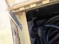
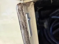
I’m going to be doing the same install, but my approach is to use metal mount points for the bolts that aid in reinforcing the SMC door material. It’s a repeat of what I did during the (new) propane tank install on our 26 footer several years ago. The struts, door, and supports still look as-new.Ashamed to share. I installed gas strut supports on my generator door today. Worked great a couple of times. Then one side broke. RATS!
Will upload closeup pix when it’s done.
Attachments

Last edited:

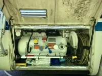
How quiet in comparison to the original unit is that new AC/Heatpump? I believe one of these is in my future.Installed a Pioneer 13.5k rooftop AC/Heatpump today. Enjoying the breeze while i start installing the new WFCO AC/DC distribution panel.
Is there any interest in the original unit?
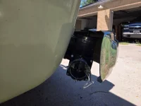
Got to play with the GMC today. I rerouted the dump piping out the rear, on the driver's side. I have a below-the-bumper hitch installed by a previous owner, and because of it, I was very limited on where I could route this. I also added another knife valve so that I have two valve protection on the discharge side of the black/waste tank. This will make dumping the tank much more convenient, and potentially much less nasty.
Attachments

Drove uneventful 700 miles roundtrip to Gettysburg PA for a bluegrass festival this weekend!
Are you ready to do Route 66 with Stephen and Sharlene Stokes and Oki and I in 2026? We want to do it in a small group so we can split up the tools, putting a little in each coach. We are hoping to get about 3,000 uneventful miles and a GMCMI Rally on that trip.Drove uneventful 700 miles roundtrip to Gettysburg PA for a bluegrass festival this weekend!
I fixed my cruise control today. I used to kinda work. So i took it out, replaced the filter material, cleaned the contacts, cleaned the vacuum passages.
Barely worked. Passed the static tests in the manual but wouldnt engage.
Yesterday i was taking it out to get it rebuilt and.....oh, theres a cracked hose!
Replaced it and boom. Works perfectly!
I had even looked for vacuum leaks before but missed it.
Now j just have to adjust it as it runs about 5mph too fast.
View attachment 15781
This is the plumbing almost ready to be installed between the new FiTech fuel injection system and the the 70 gal aluminum tank. These panels will be fastened to the outside face of the steel chassis to provide easy access if the fuel pumps or filters need to worked on if the filter fouls or the fuel pump fails.
There are (2) high pressure electric FiTech fuel pumps plumbed in parallel. All of the fittings are stainless steel with ethanol capable high pressure hose. Between the (2) pumps and the engine side are stainless steel back flow preventers to protect the pump that is not working. At the dashboard is an electric switch with 3 positions.
Up Pump #1 On With amber led pilot light
Center Both Pumps off Anti theft device
Down Pump #2 On With red led pilot light
Both pumps cannot not be function at the same time.
In case of a fuel pump failure or under performance, throw the switch to activate the second pump.
There is a pair of filters plumbed in parallel. The pale yellow filters placed st the ends will replace the plumbed bright yellow filters. The new filters are Racor 025-RAC-02 filters with a 10 micron and 25 gal per hour rating. There are shut off valve on each side of the filter so that an auxiliary fish filter can be used by flipping the 4 valves. Then, after completing the trip, a spare filter can replace the old fouled filter. At least I will not be stopped on the side of the road by a fouled filter.
I will only be using pure gasoline with no ethanol.

Now that the system is fully installed, will the COOP 455 run?
I installed a new expanded fuel tank gauge because I now have a 70 gal tank. The old gauge just didn't seem accurate enough. Rays, the gauge isn't working yet. I went to the gas station with 4 jugs and bought 21.5 gal of non ethanol gasoline. This is the first fuel in the new tank and the entire system.
To the right of the gauge is a 3 position waterproof marine grade toggle switch.
Switch up and red light is on and top pump works.
Switch center and no lights are on and no fuel pumps can work. Anti theft device.
Switch down and green light is on and lower pump works.
Power and control come from the FiTech ECU.
The 6 position blade fuse block is below the meter. There are 20amp fuses protecting the FiTech high pressure fuel pumps. If a fuse blows, flip the switch and activate the back up fuel pump.

The backed up fuel pumps and 10 micron filters are mounted on black Starboard panels fastened to the chassis. All of the metal fittings are stainless steel. The observable fuel filters are Racor filters and a clogged filter can be shut off by flipping the blue handle valves.
No teflon tape has been used. There is evidence in the recreation marine world that fragments of the tape wind up in the fuel pumps and freeze them.

The FiTech pumps are both protected by bach flow preventers so that the idle pump cannot be harmed when the other pump is working.
In all of the plumbing of this system, tank to COOP 455 motor, only one tiny leak was discovered during the inspection of the system at initial start up.

Considering that the entire system was bone dry, it only took a few attempts for the COOP 455 to fire and run. What a relief!

The COOP 455 looks happy.

This is the mock up for the COOP 455. There is no air-conditioning compressor. There are two new Balmar alternators with remote smart regulators. The red on is a 12v 160 amp alternator and the grey one below is a 48v 60 amp alternator. The power steering and water pumps are brand new. This is not the COOP serpentine system. I adapted a March Racing system and Cliff installed an balanced it. It was a time consuming installation.
I have been on pins and needles through this entire process. Will it work? Well, it does.
Soon Jacob and I will be taking the coach out on the road as soon as we figure out why one of the wheels has a locked brake. I have a theory for that.
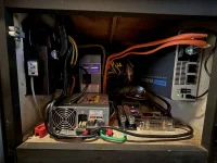
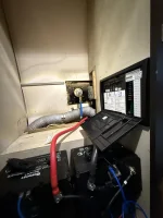
Just finishing up a full electrical cabinet overhaul. Tested the inverter with the AC running and all is working as expected!
50A service is split. Progressive Dynamics 9260 Charger/Converter, Water Heater, and Microwave are on Leg #1 which is powered by shore/gen only. Renogy PUH 3000w inverter powers Leg#2 when off-grid and allows pass-through with an automatic transfer switch when on shore of generator. Leg#2 includes the outlets, fridge and the Air Conditioning.
Reorganized everything into a WFCO AC/DC distribution panel.
I also have a Renogy 50a DC-DC w/ MPPT charger in there.
Now time to install the 4 100w CIGS panels on the roof!
Attachments
Very clean and tidy build!Just finishing up a full electrical cabinet overhaul. Tested the inverter with the AC running and all is working as expected!
50A service is split. Progressive Dynamics 9260 Charger/Converter, Water Heater, and Microwave are on Leg #1 which is powered by shore/gen only. Renogy PUH 3000w inverter powers Leg#2 when off-grid and allows pass-through with an automatic transfer switch when on shore of generator. Leg#2 includes the outlets, fridge and the Air Conditioning.
Reorganized everything into a WFCO AC/DC distribution panel.
I also have a Renogy 50a DC-DC w/ MPPT charger in there.
Now time to install the 4 100w CIGS panels on the roof!
View attachment 16033
I had a bad transmission leak. Left quite a puddle of trans fluid. So yesterday I drained and dropped the pan. As long as I was there, decided to replace the trans filter. The tube on the filter that inserts into the transmission should be .750" in diameter. So, I ordered a Wix 5882, and a ATP B40. The ATP measured out at .730". that is .030 smaller than spec and would be in danger of either leaking air into the trans fluid or dropping out of the fluid input. The Wix measured at .753". .003 larger than spec. With two "O" rings, would stay in place and seal against air intrusion.
Just FYI, here are cross #'s for other brand Trans filters. Some of these are available from Amazon.
AC Delco PF-169
Atlas 131
ATP-B40
Fram FT-1019
Motorcraft FT-19
Purolator P-219
Union B-40
Wix 51882
Price ranges from $20 to almost $50. Some kits come without the "O" ring or the Gasket.
Before I dropped the pan, I drained fluid out of a temperature sensor that I installed years ago. 5 qts
came out. I dropped the pan and lightly bolted the pan in place to see how much would drain overnight from the converter. The next morning there was an additional 3 1/2 qts. in the pan, for a total of 8 1/2 qts. The last time I put in trans fluid, (with a new rebuilt trans) I put in 14 qts. So do the math and more than half of the fluid can come out for a simple fluid change. I am using Mobil 1 ATF.
Question...Just finishing up a full electrical cabinet overhaul. Tested the inverter with the AC running and all is working as expected!
50A service is split. Progressive Dynamics 9260 Charger/Converter, Water Heater, and Microwave are on Leg #1 which is powered by shore/gen only. Renogy PUH 3000w inverter powers Leg#2 when off-grid and allows pass-through with an automatic transfer switch when on shore of generator. Leg#2 includes the outlets, fridge and the Air Conditioning.
Reorganized everything into a WFCO AC/DC distribution panel.
I also have a Renogy 50a DC-DC w/ MPPT charger in there.
Now time to install the 4 100w CIGS panels on the roof!
View attachment 16033
How is the 50A DC-DC treating your alternator/starter battery (I'm assuming you have a 100A alternator)? Is the alternator struggling at all, or overheating? I've been concerned about installing my 40A DC-DC w/MPPT for that reason (I currently use MPPT function for ground-deployed panels in addition to my primary MPPT and rooftop panels). Did you connect to the battery or directly to the alternator? I've read connecting to the battery is recommended. Just gathering data....
")
Bummer!View attachment 15931
Now that the system is fully installed, will the COOP 455 run?
I installed a new expanded fuel tank gauge because I now have a 70 gal tank. The old gauge just didn't seem accurate enough. Rays, the gauge isn't working yet. I went to the gas station with 4 jugs and bought 21.5 gal of non ethanol gasoline. This is the first fuel in the new tank and the entire system.
To the right of the gauge is a 3 position waterproof marine grade toggle switch.
Switch up and red light is on and top pump works.
Switch center and no lights are on and no fuel pumps can work. Anti theft device.
Switch down and green light is on and lower pump works.
Power and control come from the FiTech ECU.
The 6 position blade fuse block is below the meter. There are 20amp fuses protecting the FiTech high pressure fuel pumps. If a fuse blows, flip the switch and activate the back up fuel pump.
View attachment 15932
The backed up fuel pumps and 10 micron filters are mounted on black Starboard panels fastened to the chassis. All of the metal fittings are stainless steel. The observable fuel filters are Racor filters and a clogged filter can be shut off by flipping the blue handle valves.
No teflon tape has been used. There is evidence in the recreation marine world that fragments of the tape wind up in the fuel pumps and freeze them.
View attachment 15933
The FiTech pumps are both protected by bach flow preventers so that the idle pump cannot be harmed when the other pump is working.
In all of the plumbing of this system, tank to COOP 455 motor, only one tiny leak was discovered during the inspection of the system at initial start up.
View attachment 15934
Considering that the entire system was bone dry, it only took a few attempts for the COOP 455 to fire and run. What a relief!
View attachment 15935
The COOP 455 looks happy.
View attachment 15936
This is the mock up for the COOP 455. There is no air-conditioning compressor. There are two new Balmar alternators with remote smart regulators. The red on is a 12v 160 amp alternator and the grey one below is a 48v 60 amp alternator. The power steering and water pumps are brand new. This is not the COOP serpentine system. I adapted a March Racing system and Cliff installed an balanced it. It was a time consuming installation.
I have been on pins and needles through this entire process. Will it work? Well, it does.
Soon Jacob and I will be taking the coach out on the road as soon as we figure out why one of the wheels has a locked brake. I have a theory for that.
I could not get the Guage to work because the sensor is Chinese and does not work.

It is one of those unit that has a float riding up and down a shaft. We couldn't any readings or ohms from it.
Either we have to drain the tank of the 21 gals and drop it or find a way to get to it from inside the coach through the floor.
I have decided to not drop the tank. I think that I can locate it under t=either the refrigerator or the pantry and use a 4" hole saw.

It has 5 screws and no moving parts. I have to make an adapter plate. There will be no drilling of the tank with 20 gal of gasoline in it.

I think it is here.
I decided to go with a very good American sensor from BlueSea. I also cannot use the meter anymore, so I have purchased a new meter from BlueSea.

Luckily, it does not have a round face but it will fit

The face will look like this.
This is a real pain i the ass, and will cost about $500 in parts but there are positives:

A. It has the capacity of watching 4 tanks.
B. I can determine the total capacity of any tank, no mater what shape it is.
C. It will display how many gal are in the tank and the capacity of the tank.
D. It will show what percentage of the tank is full.
Therefore, with my new 70 gallon tank, each percentage is equal to 0.7 gallons. The accuracy level is plus or minus 0.35% .hat is quite a change of estimating whether the tank is between 1/2 and 3/4 full.
Recording a reading before a trip and another after a trip, I will know within 0.35% of the amount of fuel I have used and with the milage to o.1 miles, The mpg estimate may be quite accurate.
Jacob has left this afternoon and will not be available again until November, so I am now on my own again. Wish me luck