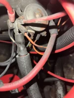
First one is in the engine bay. Guessing this orange wire is the same one appearing in the house battery bay.
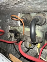
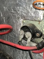
Second one is the two components in the Rear Battery Bay, third one is a close up of the specific thing I’m not sure what is.
I believe all of these are for the engine battery boost or charging from the alternator—but wanted to understand specifically before assuming.
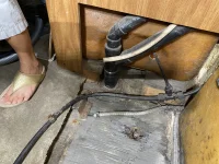
The last one—under or in front of the water tank is this connector T’s off the harness that goes to the water pump. It is not connected to anything.. What is it for? Where DID it go? It appears factory 50 years old, has a black connector On the end. The rest of that harness goes back to the water pump.
Thank you in advance.
Second one is the two components in the Rear Battery Bay, third one is a close up of the specific thing I’m not sure what is.
I believe all of these are for the engine battery boost or charging from the alternator—but wanted to understand specifically before assuming.
The last one—under or in front of the water tank is this connector T’s off the harness that goes to the water pump. It is not connected to anything.. What is it for? Where DID it go? It appears factory 50 years old, has a black connector On the end. The rest of that harness goes back to the water pump.
Thank you in advance.